|
Metallic glasses have high strengths
but are inherently brittle. To overcome
this shortfall, metallic glass composites
can be created by growing soft, crystalline
particles in the glass to make it
tougher. Processing these composites is
difficult by any known method because
they oxidize badly in open air and have
high viscosity. This article describes a
one-step casting process by which complex
components can be made, opening
the possibility for commercial and
military hardware produced from highstrength
toughened glassy composites.
INTRODUCTION
For more than two decades, bulk
metallic glasses (BMGs) have been the
subject of intense scientific study.1 By
retaining liquid-like structure in rapidly
cooled solids, BMGs possess unique
mechanical properties that have made
them desirable candidates for structural
applications.1 Lacking a dislocation-
based plasticity mechanism and
having a low stiffness, BMGs exhibit
high yield strengths and large elastic
limits. They have high hardness, excellent
corrosion resistance, and can
be processed at low temperatures into
non-sacrificial molds. These properties
have been widely exploited in commercial
applications such as electronic
casings, sporting equipment, jewelry,
materials for defense, and coatings.2
Despite a wide variety of commercial
successes obtained from die-casting
BMGs into copper molds, many
structural applications have gone unrealized, owing to the low fracture toughness,
low fatigue endurance limit, and
shear localization observed in BMGs.
For example, the most commercialized
BMG (Vitreloy 1 or LM1) has been
measured to have a plane-strain fracture
toughness, K1C, equal to 18 MPa m1/2,3
fatigue endurance limit detected at 4%
of its yield strength,4 and 0% plastic
deformation in quasi-static room-temperature
tension testing.5 Compared
with high-strength steels that exhibit
the same ultimate tensile stress, BMGs
have significantly inferior deformation
characteristics.
To improve the brittle fracture endemic
to monolithic (single-phase)
BMGs, ductile-phase reinforced
BMGs have been introduced.6,7 With
special attention paid to composition,
these BMG matrix composites form
two-phase alloys comprised of soft
crystalline dendrites distributed within
a glassy matrix. In 2001, these alloys
were demonstrated to have up to 3%
ductility in room-temperature tension
testing, while still exhibiting over 1.0
GPa ultimate tensile stress.7 More recently,
an improved understanding of
the importance of microstructure, composition,
and processing has lead to
BMG matrix composites with strength,
toughness, ductility, and fatigue endurance
limit at the upper boundary of
what is possible with crystalline metals.5,8,9 These new alloys exhibit yield
strengths as high as 1.6 GPa,8 K1C as
high as ~170 MPa m1/2,5 up to 15%
tensile ductility, and fatigue endurance
limits up to 25% of the yield strength.9
| HOW WOULD YOU... |
…describe the overall significance
of this paper?
This paper is significant because
there have been no viable
casting methods for producing
highly toughened metallic glass
matrix composites. This paper
presents original research
demonstrating that such a process
is not only feasible, but simple
and commercially scalable. This
work will lay the foundation for
an entirely new field of research in
processing metallic glasses.
…describe this work to a
materials science and engineering
professional with no experience in
your technical specialty?
Metallic glass matrix composites
have been demonstrated to have
mechanical properties equal to
or surpassing the best crystalline
metals when processed semisolidly.
However, the high viscosity
of semi-solid liquids makes die
casting difficult. In this work,
we develop semi-solid forging, a
casting process which can be used
to make net-shapes from metallic
glass composites with unrivaled
mechanical properties.
…describe this work to a
layperson?
Metallic glasses have high strengths
but are inherently brittle. To
overcome this shortfall, metallic
glass composites can be created by
growing soft, crystalline particles
in the glass to make it tougher.
Processing these composites is
difficult by any known method
because they oxidize badly in open
air and have high viscosity. In this
work, we develop a casting process
by which complex components can
be made in a one-step approach.
This opens the possibility for
commercial and military hardware
to be produced from high-strength
toughened glassy composites. |
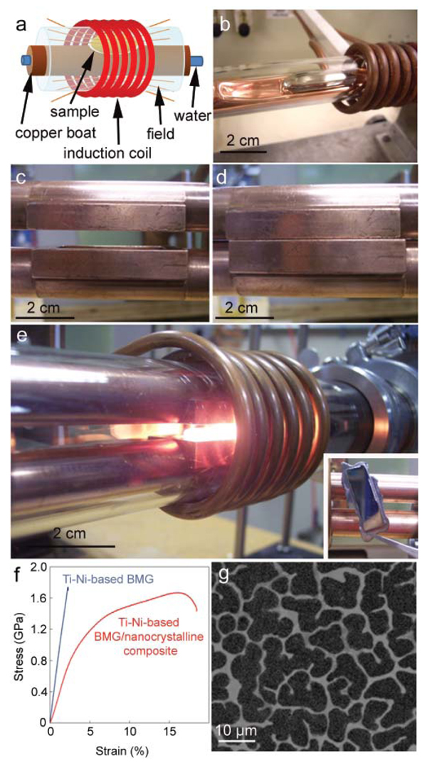
SEMI-SOLID FORGING DEVELOPMENT
The new BMG matrix composites
were developed using a novel semisolid
processing strategy, which involves holding the alloy isothermally
between the solidus and liquidus temperatures
to coarsen the microstructure
before rapidly cooling.5 This strategy,
developed at the California Institute of
Technology (Caltech), was carried out
using a water-cooled copper boat, diagrammed
in Figure 1a. A BMG sample
is heated while resting in an indentation
formed in a water-filled copper
tube. The sample is isolated in a titanium-
gettered argon environment by a
quartz tube and is heated by an induction
coil. The high thermal conductivity
of copper prevents destruction of
the boat, while radio-frequency stirring
and levitation homogenizes the sample.
Several boats have been developed to
process samples ranging in mass from
1300 g. A 25 g sample of a BMG matrix
composite within the copper boat is
shown in Figure 1b.
While the mechanical properties of
semi-solidly processed ingots from the
copper boats have been shown to have
excellent mechanical properties,5,8,9
the geometry of the resulting ingots
is highly restrictive. Samples for mechanical
testing must be machined out
of large semi-solidly processed ingots.
The only net-shape part possible with
this processing geometry is a cylinder,
and these have been formed successfully.
The major advantage of semi-solid
processing is that tough BMG matrix
composites can be formed in a one-step
approach from a partial liquid. To commercialize
these and similar alloys, a
casting process needs to be developed
to form net-shaped parts from semisolid
BMG matrix composites. Typical
die-casting into copper molds is challenging
owing to the high viscosity of
the semi-solid liquids. Thermoplastic
forming has been demonstrated as an
imprinting process for BMG matrix
composites and monolithic glasses,10,11
but complex geometries are not possible
in this route. In the current work,
we develop the concept of semi-solid
induction forging, a hybrid casting process
combining the metallurgical processes
of squeeze casting with forging.
SEMI-SOLID FORGING
Double Boat Design
Semi-solid induction forging, a technique
developed in parallel by Caltech Liquidmetal Technologies and the
University of California (U.C.) at San
Diego, is a containerless processing
strategy used to semi-solidly process
a BMG matrix composite in an inert
environment and then forge the slurry
into a mold, creating a tough net shape.
In one embodiment, employed at U.C.
San Diego, the induction forging process
is carried out by a double boat
design. In this strategy, copper molds
are welded into stacked water-cooled
copper tubes. Both copper tubes and the
molds are encased in a quartz tube and
surrounded by the heating coil. Once
the sample is processed sufficiently on
the lower mold, flexure is used to snap
the mold shut on the ingot, forging a
plate. Figure 1c-d shows the copper
molds in the open and closed position,
while Figure 1e shows a Ti-based BMG
matrix composite undergoing semisolid
processing. The resulting plate
is shown in the inset. Although the
geometry is still restrictive, the double
boat design allows for concentrated
heating and a rapid quench rate (~104
K/s), which permits the vitrification
of weak glass forming alloys (such as
non-beryllium containing composites).
The plates, which are typically 5 cm
long by 2 cm wide and 2 mm thick, are
sufficiently sized to perform compression,
tension, bending, fracture toughness,
and fatigue tests, making them a
highly desirable geometry. To illustrate
the benefits of the design, a non-beryllium
bearing BMG/nanocrystalline
matrix composite was formed in the
Ti-Ni-Cu-Mo-Sn-Si system with the
optimal microstructure for toughening
(Figure 1g). Room-temperature compression
testing, shown in Figure 1f,
demonstrates that the composite structure
exhibits ~20% total strain whereas
the parent glass exhibits none. The high
cooling rate of the double boat design
will be critical in the development of
high-melting-point, weak-glass-forming
composites.
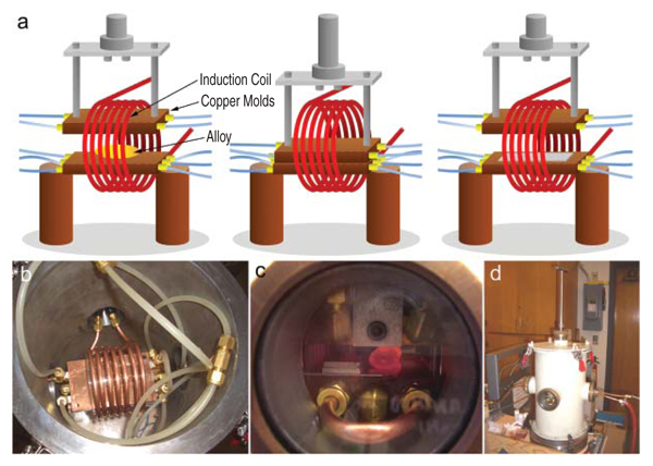
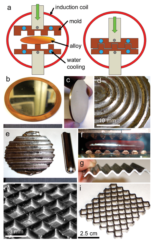
Casting Chamber Method
In the second embodiment, developed
at Caltech, the quartz tube is eliminated
and semi-solid forging is done in
an argon filled casting chamber. In this
design, two large water-cooled copper
plates serve as both the platform
for semi-solid processing and as the
mold. By performing the casting in a
vacuum chamber, sample geometries
are limited only by the diameter of the
induction coil, which range from 36
inches. After processing a large ingot
on the bottom plate, the upper plate is
lowered with a force, either through
hydraulics or a handle, as shown in
Figure 2a. However, owing to the
larger mass of the molds and slower
forging time, cooling rates are lower
than the previous design (~103 K/s).
This typically either limits samples to
thin dimensions or forces them to have
large glass-forming ability. The chamber
contains five ports used for water
lines, heating coils, viewing, plunging,
and vacuum, as shown in Figure 2b
and d. Samples ranging in mass from
6200 g have been produced, with the
only limitations being the diameter of
the induction coil and the size of the
chamber. Figure 2c shows a 100 g ingot
of a highly processable berylliumbearing
BMG matrix composite undergoing
semi-solid processing. Shims are
used to achieve a certain thickness, in
this case, 1 cm.
To investigate the success of the
semi-solid induction forging process
in comparison to samples made on
the water-cooled copper boat of Figure
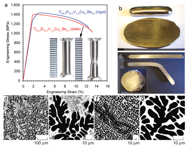
1b, tension tests were cut from a
5 mm thick, 100 g plate of the alloy DV1
(Ti44.3Zr35.2V11.8Cu6.1Be2.6 in wt.%), from
Reference 8. The typical geometry of
such a plate is that of an ellipse, with
an 8.5 cm major axis and 5.5 cm minor
axis, as shown in Figure 2b. Five-millimeter
thick square strips were cut from
a similar plate of DV1 and 3 mm diameter
gauge sections were machined
for tension testing.
After numerous tension
tests, the plates all exhibit 1014%
total strain at ultimate tensile stresses
of at least 1.4 GPa. A nominal tension
test from the semi-solidly forged plate
in comparison with an ingot from the
copper boat is shown in Figure 2a.
As shown in the inset, every sample
exhibits significant necking. Within
statistical error, the tension tests from
the semi-solidly forged plates match
those from the more idealized copper
boat, indicating the process was successful.
To demonstrate, the semi-solid
processing technique is also successful
at toughening commercial-grade material,
a 3.5 mm thick plate was produced from commercially available LM2
(Zr71.9Ti9.3Nb6Cu6.15Ni4.6Be1.6 in wt.%)
with ~5,000 ppm oxygen content. After
processing, a 3.5 mm square beam
was bent to nearly 90° without fracturing,
a demonstration which is not possible
with any monolithic BMG at that
dimension. It should be noted that the
plates are initially in contact with the
cold copper molds, and there exists a
small cold spot on the plates. This
crystalline region has been shown to
be only several micrometers thick and
has no effect on the overall mechanical
properties of the plates.
MICROSTRUCTURAL INVESTIGATION
Typical microstructures of the semisolidly
forged plates were investigated
through scanning electron microscopy
(SEM). As demonstrated previously,
the length scale of the dendrites in
relation to the critical flaw size of the
matrix is the fundamental mechanism
for toughening.5 It has been shown that
BMG matrix composites cooled on an
arc melter have a variation in dendrite
size that changes by an order of magnitude
or more, from sub-micrometer to
hundreds of micrometers. Semi-solid
ingots from the water-cooled boat always
display a coarsened microstructure,
with variation in size of less than
10% across the ingot (see Supplementary
Information, Reference 5). In
the semi-solidly forged plates in this
work, two distinct microstructures are
observed, shown in Figure 3dg for
DV1.
The first microstructure, comprised
of two different length scales, is observed
when plates are heated for the
minimum time to allow successful
forging. In these alloys, dendrite coarsening
is interrupted by forging, which
prevents the semi-solid slurry from
reaching equilibrium. The matrix material
is supersaturated with solute during
quenching, causing a finer scale of
dendrites to precipitate. However, because
the larger-scale dendrites are still
homogeneously distributed throughout
the matrix, no change in mechanical
properties is observed with the presence
of the smaller dendrites. This supports
previous observations that smallscale
dendrites have little or no effect
on toughening BMGs.5
To eliminate
the second length scale, the isothermal
processing time is increased by ~1 min.
These plates exhibit the typical microstructure
found in BMG matrix composites
directly from the water-cooled
boat. Large, coarsened dendrites are
distributed evenly throughout the matrix
(Figure 3f, g). The full size of a single
dendrite can be found by sectioning
the plate near a dendrites primary axis,
shown in Figure 3f. The length scale of
each dendrite tree, which is essentially
a single crystal of body-centered-cubic
(b.c.c.) material, is on the order of hundreds
of microns. Dendrite arms have a
diameter of ~10 μm, as shown in Figure
3g.
CASTING NET-SHAPED PARTS
To cast net-shaped parts using the
semi-solid induction forging technique,
copper molds can be attached to
the water-cooled copper blocks shown
in Figure 2a. Owing to the high thermal
conductivity of copper, the molds
do not need to be in direct contact with
cooling water but need to be in large
surface area contact with the cooled
copper blocks. This allows many lowcost
molds to be attached to the apparatus,
without changing the basic casting
platform. A diagram of net-shape
casting is shown in Figure 4a. An ingot,
initially resting on the mold, is heated
to a desired point in the semi-solid region
before the mold is closed, casting
a part. The first net-shaped part demonstrated
is the disk shown in Figure
4b. In this simple case, an ingot
of the BMG matrix composite DH1
(Zr55.3Ti24.9Nb10.8Cu6.2Be2.8 in wt.%) was
forged into a copper o-ring, making a 2
mm thick plate, 5 cm in diameter. After
polishing, the part takes on a mirror finish,
shown in Figure 4c.
To create a more complex shape,
concentric rings were lathed into an aluminum
block, 3 mm thick. An ingot of
DH1 was placed over the block, which
was then put on the lower platform in
the forging machine. The ingot was
processed and forged over the block,
creating the rings shown in Figure 3d.
Partial wetting of the aluminum to the
BMG matrix composite occurred. To
create a three-dimensional part, where
an upper and lower mold close onto the
sample, corrugations were carved into
two copper molds. An ingot of DH1
was placed across these corrugations in
the machine as demonstrated in Figure
4f. After forging, the 8 mm diameter
rods from the arc-melter are forged
into 5 cm diameter corrugated plates,
shown in Figure 4e. The strut thickness
of the plates can be varied by changing
the semi-solid processing temperature
or the forging pressure and are between
0.52 mm (Figure 4g). In another design,
an ingot of DH1 was forged into a
brass mold with a waffle pattern. The
tips of the wedge-shaped corrugations
are < 100 μm and smaller dimensions
are certainly possible, based on prior
work.11 Micro-replication of molds is
therefore possible with the semi-solid
forging technique. In addition to forging
net-shapes, more complex structures
can be assembled from parts
made using the process. In Figure 4i, a
honeycomb structure has been assembled
by cutting and soldering together
strips of the plates from Figure 4g.
These structures have high strengths
and toughnesses with low relative densities
Another useful part that can be made
using semi-solid induction forging is a
thin plate. We have observed that there
is high demand for BMG composite
plates in dimensions less than or equal
to 1 mm and yet these parts are difficult
to die-cast. Thermoplastic forming
has been used for many years to flatten
ingots of BMGs into submillimeter
thicknesses, but this has not been
accomplished with toughened composites.
Semi-solid induction forging
was used successfully to produce lowoxygen
content plates of BMG matrix
composites in thickness from 0.2510
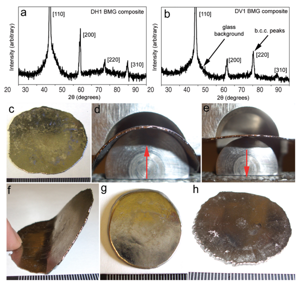
mm. To assure that the thin plates are
two-phase composites, x-ray scans
were performed on two 1 mm plates of
DH1 and DV1, shown in Figure 5a,b.
In both scans, b.c.c. peaks are superimposed
on a glassy background, indicating
the thin plates have been processed
without heterogeneous nucleation of
another phase or without total vitrification.
A 0.5 mm plate with diameter
~5 cm is shown in Figure 5c. To illustrate
the high elastic limit of the thin
plate, Figure 5d,e shows the 0.5 mm
thick plate of DH1 in a three-point
bending fixture undergoing elastic deformation. The plate can be bent
substantially, but when the force is removed,
it elastically returns to a flat
plate. To demonstrate that the thin
plates still possess the coarsened microstructure
necessary for toughening,
the same plate was clamped in a
vise and bent plastically with repeated
hammer strikes, Figure 5f. Thin plates
of beryllium-bearing BMG matrix
composites can be bent to more than
90? without fracturing. Non-beryllium
BMG/nanocrystalline matrix
composites can also be formed during
the forging process. Figure 5g shows a
Ti-Ni-V-Si composite forged into a 2
mm thick plate and Figure 5h shows a
Zr-Nb-Cu-Ni-Al alloy from Reference
12 forged into a 1 mm thick plate. In
non-beryllium composite systems, it
is challenging to quench the matrix
material as a glass without heterogeneously
nucleating crystals. As such,
we have observed that most of these
composites have a partially crystalline
matrix and are subsequently more
brittle than the beryllium-bearing versions.
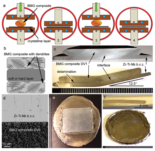
Another part that can be made using
the semi-solid induction forging
technique is a multi-layered laminar
composite, shown in Figure 6. In this
strategy, an ingot of BMG matrix composite
can be forged onto a layer of
another material, such as a soft b.c.c.
material or hard carbide. As shown
in Figure 6a, the forging process can
be repeated to either encase the other
material in a BMG composite or
to build up multi-leveled structures.
These ex-situ type composites have
been demonstrated for more than a
decade with monolithic BMGs. Wires
or particles have been infiltrated with
BMGs to make composites. This is the
first example of an ex-situ composite
made with in-situ BMG matrix composites
as one of the layers. Ex-situ
BMG composites are typically made
to toughen the brittle monolithic glass.
By using a toughened BMG composite,
new types of tough armored materials
are possible. A three layer part is
diagrammed in Figure 6b showing this
concept. To demonstrate the excellent
wetting obtained using the forging
technique, DV1 was forged onto a layer
of soft, crystalline Zr-Ti-Nb, which
is essentially the dendrite material of
DH1 and LM2.
The two-layer structure was bent in
a three-point bending configuration
to 12.5° before delamination was observed
(see Figure 6c). Scanning electron
microscopy was used to image the
interface, shown in Figure 6d, which
is intimate but has little reaction. The
process can also be modified to other
layers, such as low-melting point aluminum,
or SiC, for example. Figure 6e
shows an ingot of LM2 forged over a
1 mm thick layer of aluminum. Figure
6f demonstrates the encasing process
by which a material is completely
confined by the BMG composite. A
three-layered composite, 3 mm thick,
was formed by forging 1 mm thick
layers of DV1 over a 1 mm layer of
Zr-Ti-Nb. The cross section, shown
in the inset, demonstrates that the soft
layer has been completely encased in
the composite.
CONCLUSION
To conclude, the semi-solid induction
forging process has been demonstrated
to be one possible route for commercially
manufacturing toughened
BMG components. This work started
with the development of BMG matrix
composites that exhibited tensile ductility.
Next, semi-solid processing was
used to coarsen the microstructure to
obtain benchmark mechanical properties.
Now, semi-solid induction forging
has been used to make a wide variety
of net-shapes that have the same
excellent properties. This technique
should provide the fundamentals for
future commercial processing and for
fabrication of new alloys.
ACKNOWLEDGEMENTS
The authors thank Caltech machinists
M. Gerfen and M. Vondrus for designing
and constructing the molds.
The authors also thank J. Kang, R.
Salas, and the rest of Liquidmetal
Technologies for funding, technical
support, and alloy production.
REFERENCES
1. W.L. Johnson, MRS Bull., 24 (1999), pp. 4256.
2. See Liquidmetal Technologies, 30452 Esperanza,
Rancho Santa Margarita, CA 92688, www.liquidmetal.com.
3. P. Lowhaphandu et al., Scripta Mater., 38 (1998),
pp. 18111817.
4. C.J. Gilbert et al., Scripta Mater., 38 (1998), pp.
537542.
5. D.C. Hofmann et al., Nature, 451 (2008), pp. 10851089.
6. C.C. Hays et al., Phys. Rev. Lett., 84 (2000), pp.
29012904.
7. F. Szuecs et al., Acta Mater., 49 (2001), pp. 15071513.
8. D.C. Hofmann et al., Proceedings of the National
Academy of Sciences, United States of America, 105
(2008), pp. 2013620140.
9. M.E. Launey et al., Proceedings of the National
Academy of Sciences, United States of America, 16
(2009), pp. 49864991.
10. D.C. Hofmann et al., Scripta Mater., 59 (2008),
pp. 684687.
11. G. Duan et al., Adv. Mater., 19 (2007), pp. 42724275.
12. U. Kühn et al., Appl. Phys. Lett., 80 (2002), pp.
24782480.
Douglas C. Hofmann, visiting scientist, Henry
Kozachkov, graduate student, Joseph P. Schramm,
graduate research assistant, Marios D.
Demetriou, senior research fellow, and William L.
Johnson, Professor of Engineering and Applied
Science, are with Keck Laboratory of Engineering
Materials, California Institute of Technology, 1200
E. California Blvd., Pasadena CA, 91125; Hofmann
is also a research scientist with Liquidmetal
Technologies, 30452 Esperanza, Rancho Santa
Margarita CA, 92688. Hesham E. Khalifa, Ph.D.
candidate, and Kenneth S. Vecchio, Professor and
Chair of the department, are with the Department
of NanoEngineering, University of California at
San Diego, La Jolla, CA 92093. Dr. Hofmann can
be reached at D.C.H. dch@caltech.edu.
|
 Presenting a Web-Enhanced