 |
47 (7) (1995), pp. 46-49. JOM is a publication of The Minerals, Metals & Materials Society |
|---|
 |
47 (7) (1995), pp. 46-49. JOM is a publication of The Minerals, Metals & Materials Society |
|---|
To measure 3-D coordinates of a surface area, multiple photographs are taken of the area, and the corresponding two-dimensional (2-D) points in each picture are identified by computer. These 2-D points from the photographs are used along with the camera positions to triangulate the 3-D coordinates of the surface area.
Accuracy of the strain measurement system is dependent on several factors: camera resolution, camera position resolution, internal camera geometry, the number of photographs used in determining the 3-D coordinates, the accuracy of the initial grid pattern, etc. A systematic error analysis has been carried out by varying these parameters one at a time to determine their roles.

Figure 1. (a—left) Two video-cameras are mounted on a positioning frame where the relative camera positions are determined by encoders and the geometry of the hardware. Two views, one from each camera, are always obtained by this method. (b—center) A single camera of known position is mounted on a positioning frame. The object to be measured is placed on a rotating table. Any number of photographs may be taken from different locations by turning the table or moving the camera. Encoders record the position of the table and the camera at the time a photograph is taken. (c—right) A portable digital camera is used to take any number of photographs from any orientation. This reference object is used to determine the camera position.
A main advantage of the position-independent method is that any number of cameras can be used to take multiple photographs from different positions. These photographs can then be digitized into a computer and processed. This permits the hardware of the system to be a single camera, without the positioning equipment and encoders necessary for the existing strain measurement system. For the system currently under development, the Kodak DCS 420 digital camera is employed. This is a standard Nikon camera with a special digitizer made by Kodak. The DCS works like a standard single-lens reflex camera, allowing change of lenses, addition of filters, flash unit use, etc. The images can be directly loaded into the computer, without the need for an additional frame grabber or other digitization device. The pictures produced by this camera are roughly 2.5 times the resolution of the CCD video cameras used by the existing strain measurement system. Additional resolution could be obtained by using a standard film camera and digitizing the photographs using a scanner.
The existing system has been expanded to allow the use of any number of photographs. Originally, the system used a physical model for the triangulation equations. To facilitate quick calculation in the multiple photograph system, the existing photogrammetry coefficients are converted to direct linear transform (DLT) coefficients. This allows linear equations to be used for triangulation. A least-squares approach minimizes error when using more than two photographs. The least-squares implementation of the DLT method was reported by Marzan and Karara.(5)
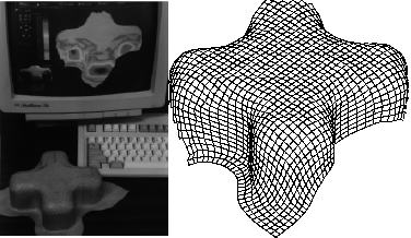
This method was used to measure a 3-D metal cross successfully, as shown in Figure 2. A total of 16,063 2-D points found in 36 photographs were used to measure 1,398 3-D points on the part. Each point on the part was located in an average of 11 photographs.

Figure 2. (a) Photograph of a three-dimensional metal cross and (b) its corresponding geometry measurement results.
The program accepts any of these parameters as input, and then performs a Monte-Carlo simulation of the appropriate measurements. The internal camera geometry is assumed to be known exactly. The internal camera parameters are those related to lens focal length, the offset of the image with respect to the camera centerline, and the size of the film or electronic array that records the image. These parameters can be determined by photographing a known object with the camera. For a given camera and lens combination, these parameters will remain nearly constant.
The photogrammetric measurement simulation program uses four accuracy parameters: one for photograph resolution, a second for camera-positioning accuracy, a third for camera-orientation accuracy, and a fourth for initial grid accuracy. This information is used by the program to produce a set of data points, which are then used to produce a set of simulated photographs. To make a simulated photograph of the specified resolution, each coordinate of each point is adjusted by a random amount. For example, if a photograph resolution of one part in 1,000 is specified, each coordinate in a photograph is adjusted by a random amount between +/-0.0005 multiplied by the photograph width or height. The random number is evenly distributed. The result of this is an even distribution of the pixel coordinate within the specified accuracy. The same method is used to adjust the camera positioning and orientation accuracy. The details of this analysis method have already been described elsewhere.(6)
After the program has computed the 3-D coordinates of all of the points visible in at least two photographs, the accuracy of these points is compared to the original data set. This is accomplished by fitting the calculated point set to the original point set by rotating and translating the set to the best fit position. This rotation and translation is done using a least-squares estimation to reduce the error between the two sets of points, following the method developed by Arun et al.,(7) and further refined by Umeyama.(8) The analysis method uses singular-valued decomposition of a matrix, and is non-iterative.
After rotating and translating the calculated point set to the least-squares best fit position with respect to the original point set, the error is calculated by computing the distance between the calculated points and the original points. The error is given with respect to the original size of the data points. The root mean-squared error of the data is used. This will produce a result of 0.001 if the overall error is one part in 1,000, in the same sense that the error is originally specified for photograph resolution, camera-positioning accuracy, and camera-orientation accuracy. Finally, the computed geometry is used to compute a simulated strain error. The output values of the program are three times the standard deviation in terms of percent true strain.
For the sample results given below, one parameter was varied while keeping all others constant in each set of calculations. The default values for the simulation were:
Three photographs
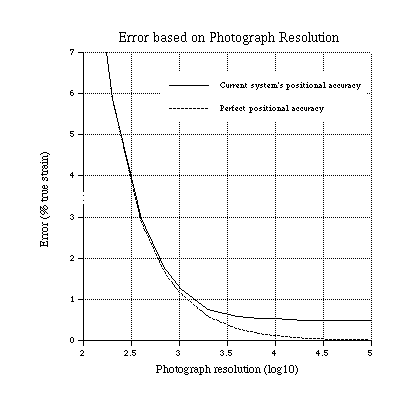
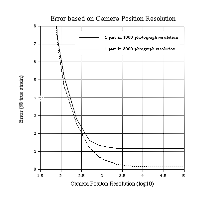
Selected results are summarized in Figures 3 and 4. On each graph the error values shown are the three standard deviation values in percent true strain. If the error is distributed by Gaussian mode, 99.7% of all results will fall below this value. Calculations were done using the DLT method developed by Marzan and Karara.(5)

Figure 3. Computed error for simulated measurement when the photograph resolution is varied.

Figure 4. Computed error for simulated measurement when the camera positioning accuracy is varied.
Presently, commercial digital cameras are limited to about 4,000 pixels across. The current system can locate points within a photograph to the nearest half pixel. This resolution would correspond to a value of 3.9 on the graph. Further improvements in photograph resolution require either switching to film cameras or an advance in digital technology. Another method of improving the accuracy would be to improve the computer processing to allow better than half pixel accuracy. This would require developing a new algorithm for locating 2-D points.
Figure 4 shows how the accuracy of the system is improved by increasing the accuracy of the camera-positioning equipment. The left side of the graph corresponds to a positioning accuracy of one part in 32 and an orientation accuracy of three degrees. The right side corresponds to an accuracy of one part in 100,000 and an orientation accuracy of 0.0009 degrees. This number is on a logarithmic scale. The value of 3.1 corresponds to the positioning accuracy of the current system, assuming three photographs and applying other reference conditions. The top line shows the error when the camera resolution is one part in 1,000, the level of the current system. The bottom line is the error with a camera resolution of one part in 8,000, which matches the best commercially available hardware. When the curves flatten out, the camera resolution has become the limiting factor, and additional positioning accuracy has almost no benefit.
The positioning accuracy can be improved by using higher resolution encoders. Encoders determine the relative camera position from some starting point. On the current system this starting point is determined using mechanical limit switches. In addition to improving the encoders, a more accurate system would also require a more accurate absolute positioning method. Through mechanical gearing and existing commercial encoders, the positioning resolution can be improved enough so that the camera resolution is the limiting factor to accuracy.
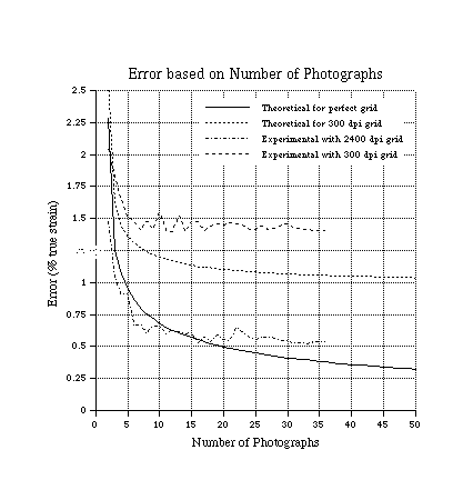
An additional simulation was performed to determine the benefits of using more than two photographs for triangulation. The previous two graphs were based on using three photographs. Figure 5 show how accuracy is improved by using from two to 50 photographs. The photograph-resolution and camera-positioning accuracy used are those of the current system. The graph also shows how accuracy is affected by different quality grids. Normally a grid pattern is applied to a sheet metal blank through an electrochemical etching or photoemulsion deposition process. These grid patterns are typically produced from an initial pattern printed from a computer. Typical printing resolutions vary from 300 dots per inch (dpi) to above 2,400 dpi. In the current study, an initial grid size of 5 mm was used, with each photograph having 20 grid squares across the image. The simulations show that there is a significant effect on error with 300 dpi grids. A simulation was also performed for 2,400 dpi grids. These results were less than 0.05% true strain worse than those obtained using an ideally perfect grid.

Figure 5. Computed and experimental error for measurements with different numbers of photographs and different grid qualities.
The reason that experimental data lie below the predicted line is most likely the result of how the simulation was implemented. The simulation result is the average measurement with all possible camera positions. When a measurement with only two photographs is made, there is an exceptionally large error when the two photographs are taken near each other. Error is reduced when the two photographs are taken with a wide angle of separation. For the actual measurements performed, a photograph separation was selected that was known to produce desirable results, and, as such, the resulting error was below the average error for such a measurement as computed by the simulation.
There are several reasons why some experimental results are worse than those predicted. The simulation assumes that all internal camera parameters are known exactly. Some parameters, such as lens focal length, are known to an extreme accuracy while other parameters, such as offset from the centerline of the lens to the center of the CCD digitizing array, are known less accurately. Inaccuracies in these parameters result in larger error than those predicted. This error is believed to be the principal cause of the discrepancy between theoretical and experimental results when using the 2,400 dpi grid. Additional experiments are necessary, however, to confirm such a trend.
With the 300 dpi grid, a systematic error was noted in the minor strains. The original grid pattern was printed on a laser printer in such a manner that the minor strain direction was along the paper feed path. If this feed rate was not constant, additional errors would be added to the initial grid. To verify this error, other printers could also be used to produce additional grids for measurement.
Based on all the parameters that have been examined in the sensitivity analysis, there are three main ways to increase the overall measurement accuracy. Accuracies are improved by increasing the number of photographs, the photograph resolution, and the positioning resolution. If the photograph resolution is improved beyond a certain point, the positioning resolution must also be improved or no additional benefit will be realized. Likewise, improving the positioning resolution will not reduce the error unless the photograph resolution is also increased. The current measurement method can be improved to achieve an accuracy of about +/-0.7% true strain, provided more than ten photographs are used per measurement.
1. J.H. Vogel and D. Lee, "The Automated Measurement of Strains from Three-Dimensional Deformed Surfaces," JOM 42 (1990), pp. 8-13.
2. M.I. Kapij et al., "Comparison of Different Surface Strain Measurement Methods Used for Deformed Sheet Metal Parts," Automotive Stamping Applications and Analysis, SP-897 (Warrendale, PA: SAE, 1992), pp. 73-85.
3. D.W. Manthey, R.M. Bassette, and D. Lee, "Comparison of Different Surface Strain Measurement Techniques Used for Stamped Sheet Metal Parts," Proceedings of International Body Engineering Conference: Body Assembly & Manufacturing (September 21-23, 1993), pp. 106-111.
4. Berthold K. Horn, "Relative Orientation Revisited," Journal of the Optical Society of America A, 8 (10) (October 1991), pp. 1630.
5. G.T. Marzan and H.M. Karara, "A Computer Program for Direct Linear Transformation Solution of the Collinearity Condition, and Some Applications of It," Proc. ASP Symposium on Close-range Photogrammetric Systems (Illinois, (1975), pp. 420-476.
6. D.W. Manthey, R.M. Pearce, and D. Lee, "Portable 3-D Data Acquisition Technology for Computer Image Generation Visual Databases," Final Report for SBIR Phase I Contract No. N61339-94-C-0058 (Orlando, FL: Naval Air Warfare Center Training Systems Division, February 1995).
7. K.S. Arun, T.S. Huang, and S.D. Blostein, "Least-Squares Fitting of Two 3-D Point Sets," IEEE Transactions on Pattern Analysis and Machine Intelligence, 9 (5) (September 1987), pp. 698-700.
8. S. Umeyama, "Least-Squares Estimation of Transformation Parameters Between Two Point Patterns," IEEE Transactions on Pattern Analysis and Machine Intelligence, 13 (4) (April 1991), pp. 376-380.
ABOUT THE AUTHORS
D.W. Manthey earned his B.S. in mechanical engineering at Rensselaer Polytechnic Institute in 1992. He is currently a product development engineer at CamSys.
D. Lee earned his Sc.D. in metallurgy and materials science at Massachusetts Institute of Technology in 1965. He is currently a professor of mechanical engineering at Rensselaer Polytechnic Institute. Dr. Lee is also a member of TMS.
For more information, contact D.W. Manthey, CamSys, 1223 Peoples Avenue, Troy, New York 12180; (518) 276-4082; fax (518) 276-6380.
Direct questions about this or any other JOM page to jom@tms.org.
| Search | TMS Document Center | Subscriptions | Other Hypertext Articles | JOM | TMS OnLine |
|---|