 |
48 (3) (1996), pp. 20-23. JOM is a publication of The Minerals, Metals & Materials Society |
|---|
 |
48 (3) (1996), pp. 20-23. JOM is a publication of The Minerals, Metals & Materials Society |
|---|
Participants who took part in this comparison exercise1-9 succeeded in creating truly impressive simulations. They demonstrated how far computer simulation has come in the last few years. More detail of their models may be found in the proceedings of the conference.10
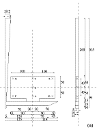
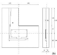
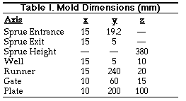
A metal charge of 2.2 kg was poured at approximately 720°C into the pouring basin. The basin was full (signaled by the escape of liquid into an overflow basin) when filled to a depth of precisely 40 mm. At this instant, the stopper was abruptly lifted clear of the basin, beginning the filling of the sprue. The temperature at which metal entered the sprue was approximately 700°C. The pouring continued uninterrupted for 3.5 s. A weir in the pouring basin ensured that only negligible bulk turbulence in the liquid was present above the entrance to the sprue. The stopper had a tapering square section to allow a close fit into the entrance of the square section sprue.
X-Ray Radiography
Mold filling was observed with a 160 kV x-ray source (1.5 mm diameter) equipped with an image intensifier. Recording was performed using a VHS 50 Hz recorder. Pouring in the lead-lined cabinet was carried out remotely, outside the cabinet, by an operator viewing the pour via a closed-circuit television camera.
Unfortunately, because of the limited field of view, not all of the mold could be viewed at one time by the video unit. The start of the pour in the region of the pouring basin is seen in Figure 2. In strict terms, this was not a required part of the benchmark test, although some participants requested details and provided a model of the basin.
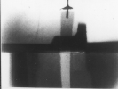
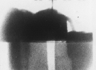
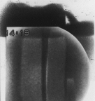
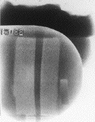
Figure 2 (left to right). Real-time x-ray radiographs of the filling of the pouring basin and sprue: (a) condition prior to pour and stopper removal, (b) stopper removal, (c) 0.24 s after stopper removal, and (d) 0.5 s after removal.
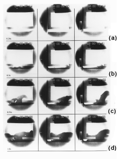
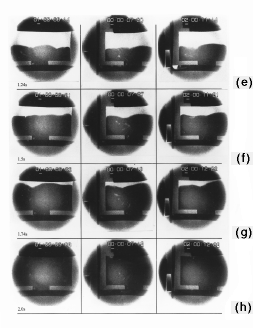
Figure 3. Three experiments run on the real-time x-ray unit to compare the progressive filling of the mold: (a) 0.24 s after stopper removal, (b) 0.5 s, (c) 0.74 s, (d) 1.0s, (e) 1.24 s, (f) 1.5 s, (g) 1.74 s, and (h) 2.0 s.
Thermal Analysis
Using thermocouple wires of 0.3 mm diameter, a junction was created by crossing the wires and spot welding, thus avoiding the formation of a bead. The excess wire was trimmed off. The wires protruding into the mold cavity were insulated with white paint (TiO2-containing emulsion paint) up to 1 mm of the junction, which was left unprotected. The paint was then fired to burn off volatiles. Care was taken to ensure that wires could not short circuit at the mold wall (a common source of error, which gives an effective temperature reading corresponding to a position close to the metal/mold interface). In any case, a certain amount of error is to be expected from the readings since it was noted that shrinkage cavities formed around the bead of the thermocouple. This will, of course, reduce heat flow and local mass of metal as well as the consequent amount of local latent heat that will be evolved. The net effect is, therefore, expected to be to shorten somewhat the overall length of freezing-time measurement.
Readings were data logged into a computer at a rate of 50 per second. Experience in the University of Birmingham indicates that such a geometry of thermocouple has a rate of response that will easily follow the thermal environment in 15 mm thick aluminum plates. Again, pains were taken to carry out two repeat experiments as identically as possible.
Materials Data
The materials data for pure aluminum were taken from Metals Handbook, Rolls Royce, Magma Gmbh, and others. The data were used by several workers. However, several values were questioned by some participants. These were a wide freezing range, which indicated that the data applied more accurately to commercially pure aluminum (98%) than the pure material intended for th e benchmark experiment. Further confusion surrounded the viscosity of liquid aluminum, which was quoted as a number (4 x 10⁻⁶) without units. Units were then added (Pa · s), unfortunately in error, based on the belief that viscosity was dynamic viscosity. In fact, the parameter was kinematic viscosity and should have been designated as m2s-1. Smithells Metals Reference Book gives the dynamic viscosity of pure aluminum at the freezing point as 1.3 x 10⁻³ Pa · s and its density as 2.385 x 10³ kgm-3.11 This yields a kinematic viscosity of 0.55 x 10⁻⁶ m2s-1.
Agreement on a database was the original aim of the exercise, and it would have greatly assisted in comparing results. It has to be admitted that this aspect of the comparison has not worked out as well as was intended. The differences in data from various sources underscores a problem that continues to hinder all efforts to simulate castings.
The measured cooling curves are presented in Figure 4. The agreement between the thermal analysis traces from two castings appears to be reasonable, although significant differences can be noted. The major differences relate to freezing times (Table II). A lthough most data agree reasonably well, site G shows a difference of nearly a factor of two. Close inspection reveals that it is melt number one that is in serious error. This value is, therefore, shown in brackets.
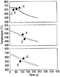
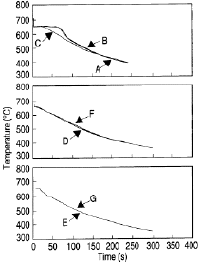
Figure 4. A consistency check for the thermal analysis results at seven thermocouple locations (Table (II) in the mold for two melts: (a—left) melt number one and (b—right) melt number two.
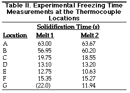
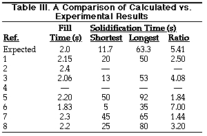
Nevertheless, the predicted freezing t imes from the first volunteer modelers displayed a wide scatter of disagreement (Table III). Where freezing time data were not tabulated by participants, approximate values were determined from their graphical results. To identify whether disagreements were simply the result of using different thermophysical data or, more fundamentally, differences in models, the longest and shortest predicted freezing times in the plates were compared. If only thermophysical data were involved, then both long and short predicted times would be expected to be increased or decreased at least approximately in proportion to the experimentally measured times. For some models, this was approximately true; in other models, however, there was considerable disagreement.
Flow
Some of the most interesting differences between the models related to the predictions of the flow of the liquid metal. Figure 5 illustrates the character of three main classes of predictions.
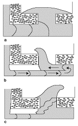 Figure 5. The primary flow patterns predicted by the computer models: (a)
highly viscous laminar flow, (b) low-viscosity laminar flow, and (c) turbulent
flow. The latter pattern most accurately fits the experimental results.
It should be noted that slight differences in behavior can be seen in experiments, even though they were designed to repeat identically. This is to be expected and is in the nature of turbulent phenomena.
Most models predict the filling time correctly at around 2.0 seconds (Table III). (It should be noted that although this time was given, it may have been used as an adjustable parameter by some workers—the time for filling was originally quoted to participants, erroneously, at 2.2 seconds.) Most models correctly predict the fast jet flow along the base of the runner during the early stages of filling the runner. This is an important aspect of the flow along a runner of this depth. Most also correctly predict the filling of the runner from its far end as the reflected wave progresses backward. This is also a key feature of flow in this part of the running system for a runner of this depth.
It is of interest that none of the models were able to predict the details of bubble formation, which characterized the junction between the overlying reflected stream and the underlying jet from the base of the sprue. As filling progressed, this partly filled runner phenomenon later evolved into a phenomenon analogous to a hydraulic jump; later still, it evolved into a simple vena contracta, which itself slowly contracted and disappeared at about 1.24 seconds. Some models gave poor predictions of the time of this disappearance.
In general, of course, most models were a long way from having the resolution to predict the bubble formation events, particularly at the hydraulic jump. Both Lewis2 and Rigaut3 correctly draw attention to this problem.
It is interesting that the only model to incorporate surface tension was that by Xu and Mampaey5 (although others claim to be able to incorporate this when necessary6). The incorporation of surface tension has thus far not been shown to be an important influence on the predictions in this exercise. However, it would seem to be a useful starting point for the detailed examination of the important and destructive phenomenon of bubble entrainment, which is so widespread in poorly designed filling systems for castings. It seems likely that a large proportion of defects in castings are the result of bubble damage.12
Finally, those modelers who also calculated the velocity vectors in the liquid during the filling of the mold cavity mostly noticed the two vortices on either side of the main filling stream. The looped trajectory of bubbles observed on the x-ray video in this area of the mold has confirmed that there are indeed such vortices. Furthermore, this circular trajectory of sequential bubbles has been so closely similar that its occurrence has suggested that the second bubble may be traveling in the oxide trail of the first bubble.13
ABOUT THE AUTHORS
B. Sirrell is a student at the Interdisciplinary Research Center in Materials at the University of Birmingham, United Kingdom.
M. Holliday is a student at the Interdisciplinary Research Center in Materials at the University of Birmingham, United Kingdom.
J. Campbell earned his D.Eng. in castings at the University of Birmingham in 1989. He is currently a professor of casting technology at the University of Birmingham.
For more information, contact J. Campbell, School of Metallurgy and Materials, University of Birmingham, Edgbaston, Birmingham B15 2TT, United Kingdom; telephone 0121 414 5215; fax 0121 414 3441; e-mail J.Campbell.MET@birmingham.ac.uk.
Direct questions about this or any other JOM page to jom@tms.org.
| Search | TMS Document Center | Subscriptions | Other Hypertext Articles | JOM | TMS OnLine |
|---|