 |
|
|---|
 |
|
|---|
 |
|---|
| CONTENTS |
A collaborative effort among engineers, instructional designers, editors, and multimedia developers, the MECD project's goal is to produce interactive courseware equivalent to subjects covered in a semester course on fluid mechanics. The modules can be used to supplement courses or can be used independently by students. Although the development of fluid mechanics concepts requires a structured, sequential presentation, the computer's ability to present concepts visually and demonstrate the dynamic flow of processes can significantly enhance the learning experience. The content contained within the modules is intended to provide students with a theoretical knowledge base that will enhance their ability to apply concepts in a variety of situations.
| Table I. Fluids Modules Currently in Development | |
|---|---|
| Modules | |
| Static Pressure | Pressure is introduced and defined, simple pressure measuring techniques are discussed, the concepts of gage and absolute pressure are introduced, and the forces on submerged surfaces are examined. |
| Buoyancy | Buoyancy forces are investigated and the stability of floating is examined. |
| Nature of Flow | Flow properties, methods of flow visualization, and descriptive terms for fluid behavior are presented. |
| Continuity | The concept of a control volume is outlined, and the mass continuity equation is developed. |
| Energy | Types of energy in a flowing fluid are presented, the energy is derived, and the concepts of energy and hydraulic gradelines are defined. |
| Momentum | The momentum equation in a flowing fluid is developed and applied to various problems. |
| Boundary Layers | Basic features of a boundary layer are introduced. Laminar and turbulent boundary layer character are explored. |
| Drag and Lift | The concepts of pressure drag and lift are introduced, and real-world examples are presented. |
| Flow in Conduits | Flow in pipes and conduits is examined, and the role of the friction factor is explored. |
| Interactive Exercises | |
| Whale Tank | Exercises that develop knowledge of pressure on a submerged surface. |
| System-Flow Line | Exercise that tests skill in identifying appropriate EGL and HGL of a flow system. |
| Introduction To Fluid Mechanics Laboratory | |
| Lab 1: Fluid Properties | Fluid properties—density and specific gravity, kinematic and absolute viscosity, and surface tension—are measured. |
| Lab 2: Velocity and Pressure | Velocity profile, volumetric flow rate, and position of mean velocity are determined for air flowing through a pipe. |
| Lab 3: Bernoulli Equation | Volumetric flow rate in a pipe is calculated using a Venturi meter or stagnation tube. Coefficient of velocity for the Venturi meter is determined and plotted versus the Reynolds number. |
| Lab 4: Sluice Gate | Volumetric flow rate is determined, and the force on a gate is calculated using the pressure profile and conservation of momentum. |
| Lab 5: Free Jet | Volumetric flow rate is measured, and the force of a jet of water on a plate is found by using a momentum beam balance. |
| Lab 6: Pipe Friction | The resistance coefficient, f, is determined for laminar flow of oil and turbulent flow of water in pipes. |
The modules are currently being disseminated via CD-ROM, with plans to adapt the modules for access via the World Wide Web. Currently, the courseware consists of ten modules covering topics ranging from fluid statics to boundary layers. In addition to the modules, a laboratory simulation has also been developed. This simulation consists of six sections with experiments covering measurements of basic fluid properties, pressure and velocity measurements, applications of the Bernoulli equation, applications of the momentum equation, and pipe friction. The fluids modules currently in development are shown in Table I.
The modules are targeted at students enrolled in undergraduate-level fluid mechanics courses. By using an active learning approach, instructional technology can benefit students of varying backgrounds and skill levels. They are able to view the same information from several perspectives, strengthening connections and transferability. Currently, the module development includes the re-evaluation of content and graphics and the implementation of new interface features allowing the modules to be used as reference resources. Specifically, companies can use the compact disk as a training tool to quickly provide a basic understanding of fluid engineering processes.
Another iteration by content specialists follows to ensure the accuracy of graphics. When the content has passed this quality-control checkpoint, the module is then programmed into the final navigational interface. Feedback is solicited from end-users and faculty and is then synthesized and used to revise the modules accordingly. The advantage of this approach to development is that it leads to a high level of product consistency, in both content and visual presentation, which is essential for sustaining a user's attention in such a technical subject area.
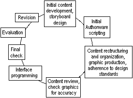 |
| Figure 1. The module design process. |
The project programmer provides an initial orientation to using the template. Reinforcement is provided via handouts, which contain screen grabs of palettes that specify particular color use (e.g., a particular blue for water and tan for oil). Some of the design specifications include consistent font sizes for each aspect of content contained in a module; the application of bold, arrows, and colored text for emphasis; formatting of equations, graphics, and graphic labels; and the use of sub- and superscript.
Authoring, graphic, and technical software is used to create a module. Each software is used to perform a specific function in the development of the modules. The primary development software used by the MECD project includes Authorware Professional for module authoring; Macromedia Director for creating animations; MathType for the development of equations and formulas; and SuperPaint, Canvas, DeBabelizer, etc., to create graphics.
An example of a typical image build is provided in Figure 2. This example is taken from the introduction on the module on boundary layers. The opening screen animates what happens when a flat plate is immersed in a flowing fluid (Figures 2a and 2b). A click of the "Continue" button highlights the laminar part of the boundary layer (Figures 2c and 2d). A further click engages the student by asking them to make a choice of the correct velocity profile. Clicking on the correct image provides positive reinforcement and some explanation (Figure 2e). Incorrect choices provide feedback and guidance, and allow users to make another choice.
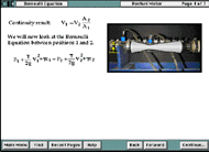
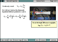
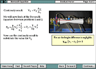
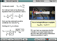
An example involving the derivation of the Bernoulli equation is shown in the screen sequences in Figure 3. As the user clicks the "Continue" button, relevant parts of the equations cancel and appropriate substitutions are made. Note that substitutions and cancellations are carried out dynamically between each of the screens shown in Figure 3.
 |
 |
| a | b |
 |
 |
| c | d |
| Figure 3. An example of the use of photographs in the image-building modules. Here, a Venturi meter is shown in a discussion on deriving the Bernoulli equation. | |
Graphics are used extensively to convey and clarify concepts. They can be used alone or as overlays on photographs to highlight particular areas. Many times portions of the equipment may not be easily seen within a photograph, and the drawings can help to clarify these regions. Graphic drawings are particularly helpful in showing where dials or switches are located—for example, the pressure taps on a Venturi meter (see Figure 3). Once the drawing overlay has been created, a graphic representation is used in place of the photograph. This allows different parts of the equipment to be manipulated and moved on screen.
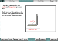
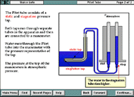
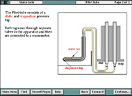
Another strategy for using graphics to represent equipment is to cut away the outer shell to show the interior. With the actual equipment this is not always feasible (e.g., showing the interior of a Pitot tube and how the static and stagnation pressure taps are separated within the main tube). This cutaway feature is illustrated in Figure 4.
 |
 |
 |
| a | b | c |
| Figure 4. An example of the cutaway features used to show the interior of equipment. | ||
Figure 5 is an example QuickTime video (click on it to play) that illustrates the nature of laminar flow by showing the flow of oil from the end of a pipe. Accompanying videos in the modules contrast this flow to intermittent and turbulent flows.
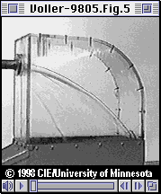 |
 |
|
|
|
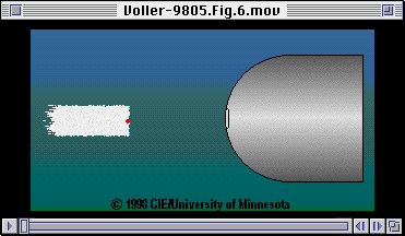
Animations are also used to demonstrate processes, particularly those that cannot be videotaped due to size or location constraints. Animations can also be broken down into steps with supporting text to highlight each process.
Figure 6 is an example animation in QuickTime format (click on the image to play). The animation illustrates the stagnation point in the flow over a bluff body. The flow of a group of hydrogen bubbles over the object is animated. The stagnation bubble, marked red, is held up at the nose of the bluff body.
Users can jump to any section via the main menu. A red triangle indicates the last section a user was in, and a checkmark indicates the last section completed (Figure 7). Users can also jump to any section in the module from within the lesson using the "Sections" pulldown menu (Figure 8).
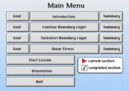 |
| Figure 7. The main menu of the module. |
 |
| Figure 8. The "Sections" pulldown menu. |
Interactivity is achieved through the use of interactive questions and problems. For example, interactive elements such as exercises, simulations, and multiple-choice questions are added after the main content has been developed. Different types of interactivity are important for students with different learning styles.
Informal student feedback during module development was provided to the development team, and revisions were made accordingly. Additionally, student surveys have been developed and implemented by the MECD development team in order to provide more specific responses (e.g., the value of navigational features and content, etc.).
Students were required to write journals tracking their impressions of the modules throughout the course. Comments included the following:
| "I think the modules should serve as a backup rather than a teacher." "It is very helpful to be able to see the processes in the labs before attending them. Modules also help in understanding the lab afterwards as well." "I am somewhat skeptical about these computer modules." "I was pleasantly surprised at the clarity it (lab module) provided in demonstrating the lab objective and procedures." "I have changed my mind. I think they really help. They clarify the labs and lecture and book." "I like the fact that concepts are shown visually, and I think it saves the professor some time to cover more information." "I would rather have the professor lecture to the class while going through the module. In this kind of lecture he adds key points, expands upon ideas. I can also ask him for clarification." |
Gramoll, K., and J. Craig. "Teaching a Multimedia Course in Engineering." Ibid. pp. 2578-2584.
Horswill, J. "An Electronic Book Project: The Fundamentals of Interfacial Engineering." Ibid. pp. 1795-1799.
MECD Group. "Computer-Based Multimedia Applications in the Fundamentals of Fluid Mechanics." IEEE/ASEE Frontiers in Education Conference. Salt Lake City, UT: American Society for Engineering Education, 1996.
Ribando, R.J. "A Partial Studio Model for Teaching Undergraduate Heat Transfer." IEEE/ASEE Frontiers in Education Conference. Ibid. 1996.
Yusaf, I., and K. Gramol. "Case Based Multimedia in Engineering Education." Investing in the Future, Salt Lake City, UT: American Society for Engineering Education, 1995.
ABOUT THE AUTHORS
Vaughan R. Voller earned his Ph.D. in applied mathematics at the University of Sunderland, United Kingdom, in 1980. He is currently a professor with St. Anthony Falls Laboratory of the University of Minnesota. Dr. Voller is a member of TMS.
Sheila J. Hoover earned her M.S. in instructional design and technology at the University of Minnesota in 1993. She is currently an education specialist/instructional designer with the Multidisciplinary Engineering Curriculum Development Center at the University of Minnesota.
Joan F. Watson earned her M.A. in music performance from Northwestern University in 1978. She is currently a project coordinator/instructional designer with the Multidisciplinary Engineering Curriculum Development Center at the University of Minnesota.
For more information, contact V.R. Voller, University of Minnesota, 500 Pillsbury Drive, Minneapolis, Minnesota 55455; (612) 625-0764; fax (612) 626-7750; e-mail volle001@maroon.tc.umn.edu.
Direct questions about this or any other JOM page to jom@tms.org.
| Search | TMS Document Center | Subscriptions | Other Hypertext Articles | JOM | TMS OnLine |
|---|