 |
|
|---|
 |
|
|---|
| CONTENTS |
|---|
 +
+  2) equiaxed and fully lamellar forms possess attractive high-temperature properties. Creep deformation and cavitation damage in these microstructures were simulated and analyzed here using finite-element techniques. Nonlinear viscous creep deformation was modeled using published creep data. Creep-constrained grain boundary cavitation was also analyzed based on the Rice and Needleman model. The modeling results show that the low strain rates and relatively long creep life observed experimentally for fully lamellar TiAl can be primarily due to the suppression of grain-boundary sliding as a result of the serrated nature of the grain boundaries. These, as well as other findings related to the roles of lath-boundary sliding and cavitating facet interaction, are reviewed.
INTRODUCTION
Ordered intermetallics based on aluminides constitute a unique class of structural materials for use at high temperature in hostile environments. Their promising properties include low density, excellent elevated-temperature strength, and resistance to oxidation and corrosion. Intermetallics based on titanium aluminides are envisaged as future-generation engine materials for transatmospheric vehicles. Two-phase gamma titanium aluminides are identified as a unique class of structural materials for aerospace application. The two distinct types of two-phase ( +
+  2) titanium aluminides studied here are lamellar microstructures, with alternating lath colonies of
  2 and
2 and  phases, and equiaxed microstructures, marked by isolated
  2 grain in a sea of
  grains. At present, a great deal of research is underway to gain a thorough understanding of the mechanical behavior of these materials.1
The experimental study of the creep deformation2-5 and rupture6-8 of these materials has been investigated by several researchers. The results of these efforts suggest that the fully lamellar microstructure is generally stronger than equiaxed microstructures for dual-phase titanium aluminides at elevated temperatures. In order to have a better understanding of the creep deformation and subsequent damage mechanisms in titanium aluminides, numerical simulation and analyses were performed using finite-element (FE) techniques.
CREEP DEFORMATION
Model Formation
 |
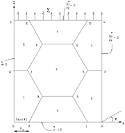
| Figure 1. A schematic showing the present unit cell with boundary conditions. |
Several models were considered with and without the grain-boundary sliding. Grain-boundary sliding under the action of externally applied stress was simulated using slide lines along the grain boundaries. In all of the analyses performed, it was assumed that the grain-boundary sliding takes place relatively freely (i.e., frictionless sliding), compared to the resistance against other creep-deformation mechanisms. This is a reasonable assumption for grain-boundary sliding as long as the temperature is sufficiently high, and the stress level, as well as the creep strain rate, is low.
The possibility of lath-boundary sliding in a fully lamellar model under creep conditions was also modeled in a previous study.10 The overall strain rates in such models were compared with the overall strain rate in fully lamellar models in the absence of any grain- or lath-boundary sliding. It was observed that the lath-boundary sliding gives rise to an overall strain-rate magnification of 100 times the overall strain rate obtained in the model without any boundary sliding. A comparison of these strain rates with the experimental data showed that the strain rate obtained in the model with lath-boundary sliding is unrealistically high, while the strain rate observed in the fully lamellar model in the absence of boundary sliding is similar to the experimental data. Moreover, transmission electron microscopy observations revealed that the density of superdislocations does not change along the lath boundaries during the course of creep deformation.11 Based on these findings, it is unlikely that the  /
/ phase boundary sliding occurs to any great degree during creep deformation.
 | (1) |
where  e is the von Mises stress, A is a constant for a given material, and n is the stress exponent.
The effect of grain-boundary sliding on creep deformation and damage has been found to be important for many materials.12 Grain-boundary sliding increases the level of stress inside the grains, which results in an increase in the overall strain rate of the material. As a result of grain-boundary sliding, Equation 1 takes the following form13-15
 | (2) |
 |
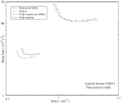
| Figure 4. A comparison of overall strain rate vs. strain for dual-phase equiaxed and fully lamellar TiAl microstructures. Models that include grain-boundary sliding are indicated by "GBS." |
The overall strain rate obtained in the duplex and fully lamellar microstructures are shown in Figure 4. Both microstructures exhibit nearly identical strain rate in the presence of grain-boundary sliding. However, the duplex microstructure exhibited a lower overall strain rate compared to that in the fully lamellar model in the absence of grain-boundary sliding.
GRAIN-BOUNDARY CAVITATION
Model Formation
At very low tensile stresses, grain-boundary diffusion is the dominant mechanism, and creep flow is negligible.19 The volumetric growth rate of equilibrium-shaped cavities in this case is given after Needleman and Rice19 as
 | (3) |
Where,  n is the average normal stress on the cavitated grain boundary. The sintering stress,
 s, is given as
 s = 2
s = 2
 ssin (
 /a, where
  s is the surface free energy. The cavity tip angle,
 , is obtained from the relation
 | (4) |
where  b is the grain-boundary free energy. The effective area fraction of the cavitated grain boundary,
  , is given in Reference 21.
 |
Tvergaard22 has shown that the rate of void growth due to dislocation creep under low triaxial stress conditions is given by
 | (5) |
where  n = 3/2n, and
  n = (n - 1)(n + 0.4310/n2). The parameters
  m and
m and  e are the remote mean stress and Mises stress, respectively. The function h(
 ) accounts for the shape of the cavity, which is given as
 | (6) |
The total volumetric cavity growth rate can be determined by summing Equations 3 and 5; thus
 | (7) |
The corresponding rate of change in cavity radius is given as
 | (8) |
The growth of cavities on grain-boundary facets results in the separation of grains by the plating of atoms out onto the grain boundary from the surface of the cavities.23 The average separation  can be expressed in terms of cavity volume V and cavity half-spacing b as
  = V/
= V/ b2. Therefore, the rate of separation of the grains,
  , is
, is
 | (9) |
where  is given by Equation 7. Van der Giessen and Tvergaard24 have shown that the rate of change of void spacing,
  , can be correlated with the true strain rate,
  p, in the grain-boundary plane as
 | (10) |
It is assumed that the spatial distribution of the cavitating facets follows a periodic order so that we can confine our analysis to a unit cell. Only transverse grain boundaries with respect to the direction of externally applied stresses are assumed to cavitate. Figure 1 shows one quarter of the unit cell with boundary conditions. It can be seen from this figure that the dimensions of the unit cell are specified in terms of the number of grains in the y direction, m1; the number of grains in the z direction, m2; and the initial radius of the grain-boundary facets, R0.
The boundary conditions of the present models, illustrated in Figure 1, are implemented in such a way that the grain boundaries can slide freely without separation. Nodes at the grain-boundary triple points are pinned together to meet strain compatibility conditions. Symmetry boundary conditions,  and
and  , are applied on sides OF and OA of the cell OACF, respectively. This unit cell forms a larger cell when reflected about OA and OF, and repetition of this process builds a representative bulk material sample. Nodes on cell boundary AC are constrained to have the same y displacement, u, while nodes on boundary CF are constrained to have the same z displacement, v, at all times. Stress,
  , is applied on boundary CF. External stress is maintained constant all the time. A detailed discussion of the problem formulation and method of analysis is given in Reference 25.
Results
Figure 5 shows the fringe pattern of normalized axial stress in a dual-phase equiaxed model with and without the presence of grain-boundary sliding. It is evident from Figure 4 that the presence of the  2 grain at the center of the unit cell leads to a stress concentration at the triple point K. Similar stress concentration, with a bigger zone, results in the presence of grain-boundary sliding, as seen from Figure 5b. It is apparent that this stress concentration could aid in nucleating new cavities at grain boundary KB.
 2 laths that are more closely aligned with the applied stress direction redistribute more stress to the adjacent
  laths.
Figure 6b illustrates the normalized axial stress distribution in the same model in the presence of grain-boundary sliding. Grain-boundary sliding resulted in higher stress concentration compared to that in the absence of grain-boundary sliding.
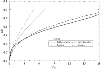
 = a/b, as a function of normalized time, t/tE, is illustrated in Figure 7 for the present models. It is evident from this figure that grain-boundary sliding substantially reduces the cavity coalescence time for all the microstructures. Cavity growth in a dual-phase equiaxed microstructure is found to be faster as compared to that in the fully lamellar microstructure for both cases, with and without grain-boundary sliding.
The effect of interaction between the cavitating facets was also investigated in the fully lamellar models.26 It was observed that the effect of interaction is more pronounced when cavitating facets are on the neighboring transverse grain boundaries. Conversely, when cavitating facets are not the nearest-neighbor grain boundaries, a negative interaction (in that the cavity growth is lower that that in an isolated facet) can be produced between the two facets. However, a negative interaction is only predicted in the presence of grain-boundary sliding.
 |
| Figure 7. A plot of creep damage at facet one of duplex and fully lamellar models vs. normalized time. |
The effect of lamellae orientation on creep cavitation damage in the fully lamellar microstructures is found to be insignificant in the presence of grain-boundary sliding. However, the isostress orientation of laths in the grains adjacent to the cavitating grain boundary is found to delay the cavity growth and, thereby, increases the rupture time. However, this beneficial effect may not be seen for microstructures with random lath orientation.
ACKNOWLEDGEMENT
Support for this work from the U.S. Air Force Office of Scientific Research under grant number F49620-94-0137 is gratefully acknowledged. The authors thank the Lawrence Livermore National Laboratory for providing the finite-element codes through their software collaborators program.
References
1. Y.M. Kim, JOM, 46 (7) (1994), p. 30.
2. R.E. Schafrik, Met. and Mat. Trans. A, 8 (1977), p. 1003.
3. M.F. Bartholomeusz, Q Yang, and J.A. Wert, Scripta Met. et Mat., 29 (1993), p. 389.
4. Helmet Mehrer, Mat. Trans., JIM, 37 (1996), p. 1259.
5. D.S. Shih et al., Microstructure/Property Relationships in Titanium Aluminides and Alloys, eds. Y.W. Kim and R.W. Boyer (Warrendale, PA: TMS, 1991), p. 135.
6. S. Mitao, S. Tsuyama, and K. Minakawa, Microstructure/Property Relationships in Titanium Aluminides and Alloys, eds. Y.W. Kim and R.W. Boyer (Warrendale, PA: TMS, 1991), p. 297.
7. W.O. Soboyejo and R.J. Lederich, Structural Intermetallics, eds. R. Darolia et al. (Warrendale, PA: TMS, 1993), p. 353.
8. R.W. Hayes and P.L. Martin, Acta Met. and Mat., 43 (1995), p. 2761.
9. B. Engelmann and J.O. Hallquist, NIKE2D User Manual (Lawrence Livermore National Laboratory, April 1991).
10. A. Chakraborty and J.C. Earthman, Met. and Mat. Trans. A, 28A (1997), p. 979.
11. M. Es-souni, A. Bartels, and R. Wagner, Mat. Sci. and Eng. A, 171 (1993), p. 127.
12. H. Riedel, Fracture at High Temperatures (New York: Springer-Verlag, 1986).
13. F. Ghahremani, Int'l. J. of Solids and Structures, 16 (1980), p. 847.
14. K.J. Hsia, D.M. Parks, and A.S. Argon, Mech. of Mat., 11 (1991), p. 847.
15. F.W. Crossman and M.F. Ashby, Acta Met. and Mat., 23 (1975), p. 425.
16. P.M. Anderson and J.R. Rice, Acta Met. and Mat., 33 (1985), p. 409.
17. G.J. Rodin and M.W. Dib, Advances in Fracture Research, eds. D.M.R. Taplin et al. (New York: Pergamon, 1989), p. 1835.
18. W. Beere and M.V. Speight, Mat. Sci., 12 (1978), p. 172.
19. A. Needleman and J.R. Rice, Acta Met. and Mat. 28 (1980), p. 1315.
20. A.C.F. Cocks and M.F. Ahsby, Progress in Mat. Sci., 27 (1982), p. 244.
21. T.-L. Sham and A. Needleman, Acta Met. and Mat., 31 (1983), p. 919.
22. V. Tvergaard, J. Mech. and Phys. of Solids, 32 (1984), p. 373.
23. J.R. Rice, Acta Met. and Mat., 29 (1981), p. 675.
24. E. van der Giessen and V. Tvergaard, Mech. of Mat, 17 (1994), p. 47.
25. A. Chakraborty and J.C. Earthman, Acta Met. and Mat., 45 (1997), p. 4615.
26. A. Chakraborty and J.C. Earthman, Met. and Mat. Trans. A, 29A (1998), p. 957.
ABOUT THE AUTHORS
A. Chakraborty earned his Ph.D. in engineering in 1997 from the University of California at Irvine. He is currently a scientist with Tanner Research.
J.C. Earthman earned his Ph.D. in materials science and engineering from Stanford University in 1985. He is currently an associate professor in the Department of Chemical and Biochemical Engineering and Materials Science at the University of California at Irvine.
For more information, contact A. Chakraborty, Tanner Research, 180 North Vindeo Avenue, Pasadena, California 91107; (626) 432-5766; fax (626) 432-5705; e-mail anirban@tanner.com.
Direct questions about this or any other JOM page to jom@tms.org.
| Search | TMS Document Center | Subscriptions | Other Hypertext Articles | JOM | TMS OnLine |
|---|