 |
51 (1) (1999), pp. 27-31. |
|---|
 |
51 (1) (1999), pp. 27-31. |
|---|
 |
| CONTENTS |
|---|
This article provides an overview of structural changes that occur during the hot working of superalloys and provides insight into the use of precipitated particles and other thermomechanical factors to achieve desired structures. Examples will focus primarily on alloys 718 and 720, which are iron-nickel and nickel-based alloys, respectively. The availability of a second phase to control grain size is a characteristic of some iron-nickel- and nickel-based superalloys that is not usually available to cobalt-based superalloys; processing with and without the use of a precipitated phase that influences microstructures will be illustrated by the use of these examples.
Structural requirements for semi-finished products, such as billet, bar, rod, plate, and sheet, vary with alloy and application. Some of the factors influencing these requirements are ultrasonic inspectability (finer grain structures are necessary to meet the more stringent specifications for ultrasonic inspection), downstream finishing operations (e.g., forged plus machined or machined only), forging practices for the final component, and the mechanical properties required in the final component.
The final optimization of component mechanical properties is usually a compromise between various characteristics, biasing toward those properties considered to be design limiting. Hot-working conditions are designed to enhance those microstructural characteristics known to favor the more critical properties, but with minimal jeopardy to other properties. Grain size is a classic consideration, with coarser grain size favoring creep strength and crack-growth resistance, and a fine-grain structure favoring improved low-cycle fatigue life and tensile yield strength.
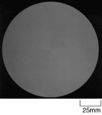 |
| Figure 1. The transverse macrostructure of forged 127 mm diameter alloy 718. |
 ' solvus temperature and volume fraction of
  ' are increased. The greater volume fraction of
  ' also reduces ductility.
There are a number of hot-workability tests available to establish hot-working ranges and measure the ductility and strength within the hot-working range. A popular test is the Gleeble tension test,14 where the specimen is resistance-heated according to a programmed heating cycle and pulled in tension at a programmed strain rate. Ultimate tensile strength and reduction in area are measured. When evaluating temperature ranges for hot-working superalloys, it is usually not sufficient to merely heat directly to various temperatures; it is also necessary to acquire on-cooling data, where specimens are tested after cooling from a temperature corresponding to the furnace temperature in a hot-working operation. There is lower ductility at 1,027°C on cooling from 1,138°C for alloy 720 relative to alloy 520 (Ni-14Cr-12Co-6Mo-3Ti-2Al-1W-0.05C-0.005B). Hot workability is lowest in the ingot condition and improves as more deformation is imparted to the ingot.
| INGOT PRODUCTION | |||||||||
|---|---|---|---|---|---|---|---|---|---|
| Superalloys are generally made using vacuum-induction melting (VIM) followed by either vacuum-arc remelting (VAR), electroslag remelting (ESR), or a combination of ESR followed by VAR (triple-melted).2 VIM melting ensures that the raw materials, consisting of virgin and revert, are homogeneously mixed together in the electrode, but it does not provide a solid product that is suitable for subsequent hot working. VAR entails the continuous melting of a consumable electrode under vacuum into a water-cooled copper crucible by a direct current (d.c.) arc to produce an ingot with a structure and chemistry superior to the electrode being melted. The VAR process reduces the levels of volatile tramp elements. In ESR, an alternating current (a.c.) is passed through a consumable electrode, a molten slag immersing the tip of the electrode, and a continuously solidifying ingot. The current heats the slag above its melting temperature; the molten slag then melts the electrode. An advantage of ESR is that the molten slag acts as a refining agent to remove oxide clusters.3-7 VAR is less prone to positive segregation than ESR and is, therefore, capable of melting larger ingots. However, ESR is more resistant to the formation of "white spots" or negative segregation.8 Compared to VAR, ESR provides better retention of volatile elements, such as magnesium, which may favorably affect ductility. Conversely, volatile elements detrimental to ductility (such as lead and bismuth) are not removed as effectively in ESR. Triple melting combines the advantages of both ESR and VAR.9
The maximum ingot cross section that can be melted without unacceptable segregation is dependent on alloy composition. Superalloys highly prone to segregation are limited to diameters on the order of 500 mm, while some superalloys can be melted to diameters of 1,000 mm or larger. A popular ingot size for segregation-prone alloys such as 718 (Ni-18.5Fe-18Cr-5.3Nb-3Mo-0.9Ti-0.5Al-0.03C) and 720 (Ni-18Cr-14.8Co-5Ti-3Mo-2.5Al-1.2W-0.04Zr-0.02B-0.02C) is 500 mm in diameter and approximately 4.5 tonnes in weight.
Figure Aa shows a longitudinal cross section of an as-cast alloy 718 ESR ingot that is 160 mm in diameter. Columnar grains are oriented perpendicular to the advancing profile of the molten pool. Equiaxed grains near the center are quite large. The grain structure is similar to that in larger diameter ingots. As-cast ingots can exhibit extensive microsegregation: Figures Ab and Ac show the microstructure at the mid-radius location of the ingot. The low-magnification micrograph (Figure Ab) reveals a dendritic solidification pattern with numerous primary dendrite spines and secondary arms. The higher magnification in Figure Ac reveals the enriched interdendritic regions, which represent the last metal to solidify; these regions are enriched in niobium as well as both molybdenum and titanium. Previous work by Radavich et al. has shown that niobium can vary from 2% in the dendrite spines to 10% in the interdendritic regions for alloy 718 ingots.10 Because of this enrichment, an extensive Laves phase is precipitated in the interdendritic regions; carbides are also present in these locations. The light-etching Laves phase can be represented as A2B, where "A" atoms are primarily nickel, iron, and chromium, and the "B" atoms are niobium, molybdenum, and titanium. The type and extent of microsegregation is very alloy-dependent. For example, the degree of niobium segregation has been related to the difference in temperature between the liquidus and the solidus.11 It was found to increase from 5% in alloy X-750 (DT = 37°C) to 14% in alloy 625 (DT = 75°C) and 21% in alloy 718 (DT = 100°C). Titanium nitrides have a high melting point and solidify with primary dendrites.12 Secondary dendrite arm spacing is influenced by local solidification rates, with faster solidification rates resulting in finer secondary arm spacing.10,11 Dendrite arm spacing is important commercially because the larger the spacing, the longer the time required for homogenization heat treatment.10 Homogenization is the heat treatment of an as-cast ingot at high temperatures and long times to reduce microsegregation. Since homogenization is a diffusion-controlled process, the homogenization temperature is selected to be as high as possible without reaching the incipient melting temperature. The time at temperature can vary from a few hours to days. Slow heat-up rates are frequently used to avoid cracking from thermal stresses.
The effectiveness of homogenization is illustrated in Figure B, which shows the structure following homogenization of the as-cast ingot presented in Figure A. Complete dissolutioning of the Laves phase has taken place; niobium and other elements are relatively uniformly distributed. When Laves phase goes into solution, some porosity may result. However, this porosity is not interconnected and is quickly healed during hot working. Although homogenization is highly effective, it does not eliminate microsegregation, even at very long times. Also, it does not eliminate or redistribute nitrides or many carbides and carbonitrides. As a result, there are practical and economic constraints on the length of homogenization cycles. Grain growth can occur during homogenization, as indicated in Figure C, which shows a transverse section of the ingot before and after homogenization. |
|||||||||
In commercial practice, initial hot-working furnace temperatures during ingot breakdown are usually relatively high to provide maximum thermal energy for recrystallization. Dynamic, metadynamic, and static recrystallization all can take place. These temperatures are usually above the solvus temperature for precipitating intermetallic phases. However, it has been noted that the hot working of Udimet 700 was improved by the precipitation of  ' prior to hot working, followed by hot working below the
  ' solvus.22
Recrystallization starts preferentially at grain boundaries, as shown in Figure 2, which represents the mid-radius structure of the alloy 718 ingot shown in Figures B and C. It was radial-forged on a GFM machine from 160 mm to 140 mm in diameter with no reheats at 1,107°C. In addition to a grain-boundary "necklace" structure, recrystallization has started at some carbide, carbonitride, and nitride particles. Also, isolated regions of some grains exhibit more extensive recrystallization (Figure 2b). At the surface, where the temperature is lower due to cooling, only a small amount of recrystallization takes place (Figure 2c). When the structure was reheated at 1,107°C, grain growth and additional recrystallization occurred (Figure 2d). With repeated deformation and reheating, a fully recrystallized structure develops. To avoid excessive grain coarsening, the furnace temperature is usually dropped after the initial ingot breakdown. The amount of deformation after the last reheat is kept sufficiently large to prevent the formation of a duplex structure consisting of coarse, unrecrystallized grains (formed during reheating) together with finer recrystallized grains (formed during hot working).
When fine-grain billet structures are desired for alloy 718, final processing is done at temperatures close to the  solvus temperature in the range of 982-1,010°C. A typical billet structure for alloy 718 billet that is 254 mm in diameter is shown in Figure 3; the original ingot diameter was 508 mm. It is common for some unrecrystallized grains to be present at the billet surface due to die chilling. Fortunately, much of this surface region is removed during final conditioning by grinding and/or peeling. Finer grain structures can be achieved with similar processing for smaller billet and bar cross sections because of increased deformation and faster cooling rates.
 " with some contribution from
  '. The
  " is coherent and has a body-centered-tetragonal crystal structure, while
  ' has an ordered face-centered-cubic crystal structure. The stoichiometry of both can be represented as Ni3(Nb,Ti,Al). The
  " and
" and  ' phases in alloy 718 are both metastable. The stable precipitate phase is
  , which has an incoherent orthorhombic crystal structure of Ni3(Nb,Ti). It forms as intergranular lathes along (111) planes and/or at grain boundaries.
In the Minigrain process, following initial ingot breakdown, a conditioning heat treatment precipitates  phase in an acicular pattern (Figure 4a). This heat treatment lasts up to approximately 24 hours at a temperature of 900°C, which is at the knee of the time-temperature-transformation diagram.27 Subsequent working is performed at temperatures less than the
  -solvus, with some deformation below the recrystallization temperature. A fine-grained structure is generated during dynamic and static recrystallization. Significant static recrystallization can take place during reheating. The needle-like
  -phase becomes globular and restricts grain growth. An example of the final microstructure is shown in Figure 4b for 127 mm diameter billet. The benefits of using the
  process to control grain size in the billet are improved ultrasonic inspectability and a more uniform microstructure in the finished forging.24
 |
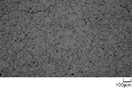 |
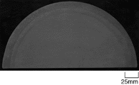
| Figure 6. The macrostructure of forged alloy 720 showing a ghost grain structure appearing along a portion of the outside surface. | Figure 7. The microstructure of spray-formed alloy 718. |
 ' solvus temperature. This affords the opportunity to use coarse
  ' particles to control grain size. An irregular and varied
  ' morphology forms during hot working below the
  '- solvus when billet grains are larger and a remnant as-cast structure prevails. This is documented in Figure 5a, which shows a typical
  ' structure for an intermediate alloy 720 billet from a forged 500 mm diameter ingot. During subsequent forging and reheating, the
  ' precipitates change morphology to become more spherical and more uniformly distributed. A typical structure of a 165 mm diameter billet is shown in Figure 5b. Some isolated grains in alloys such as alloy 720 can be extremely resistant to recrystallization during subsolvus forging. These grains undergo large amounts of deformation, as is indicated by the large aspect ratios (Figure 5c).
An interesting macrostructural feature that can develop during the conversion of alloys like alloy 720 is a ghost grain structure (Figure 6). Microstructural evaluation reveals a fine-grained structure with the ghost grains not being apparent at the microstructural level.
Radial-forging operations are frequently used in the final stages of billet production because of the improved control over process variables, such as processing temperature, strain, and strain rate. Finite-element process models28-30 can be used to predict the temperature distribution throughout the forged billet during each pass of the radial-forging operation. With these predictions, it is possible to design hot-working practices to provide the desired microstructural features.
Spray forming is a recent development under evaluation for producing superalloy ingots. In this process, a molten stream is atomized to produce droplets that are directed toward a collector to form an ingot. Nitrogen or argon can be used as the atomizing gas. The grain structure of spray-formed ingots is significantly finer than that of cast ingots. Compare the structure shown in Figure 7 from a 400 mm diameter preform with that of the 160 mm diameter cast ingot in Figure Ac. Consequently, minimal homogenization is necessary for spray-formed material, and much less deformation is required for conversion to a fine-grained structure.
 |
 |
 |
| a | b | c |
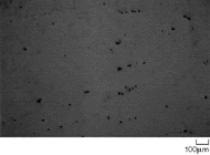
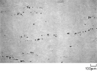
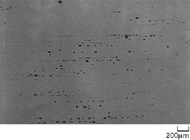
| Figure 8. The typical appearance of carbides in alloy 718 in (a) cast 500 mm diameter ingot, (b) hot-worked 254 mm diameter billet, and (c) hot-worked 127 mm diameter billet. | ||
During an inspection of final billet, structural anomalies are sometimes revealed. They generally have no impact on properties provided they meet predetermined specified standards for acceptance. Anomalies include tree ring patterns, center dendritic patterns, white spots, and banding. The appearance of some anomalies, such as solidification white spots, are highly dependent on hot-working practices.8
References
1. E.F. Bradley, Superalloys, a Technical Guide (Metals Park, OH: ASM, 1988).
2. A. Choudhury, Vacuum Metallurgy (Materials Park, OH: ASM, October 1990).
3. R.D. Kissinger, "Trends and Near Term Requirements for GE Aircraft Engines-Titanium and Nickel Base Disk Alloys," Electron Beam Melting and Refining-State of the Art 1991, ed. R. Bakish, (Reno, NV: 1991), pp. 31-40.
4. R.K. Hopkins, "Method and Apparatus for Producing Cast Metal Bodies," U.S. patent 2,191,479 (1945).
5. K.O. Yu and J.A. Dominique, "Control of Solidification Structure in VAR and ESR Processed Alloy 718 Ingots," International Symposium on the Metallurgy and Applications of Superalloy 718, ed. E. Loria (Warrendale, PA: TMS, 1989), pp. 33-48.
6. J.K. Tien, ed., Superalloys, Supercomposites and Superceramics (Boston, MA: Academic Press, 1989), pp. 49-97.
7. J.T. Cordy, S.L. Kelley, and L.W. Lherbier, "Chemistry and Structure Control in Remelted Superalloy Ingots," 1984 Vacuum Metallurgy Conference on Specialty Metals Melting and Processing, ed. G.K. Bhat and L.W. Lherbia (Warrendale, PA: ISS, 1984), pp. 69-74.
8. L.A. Jackman, G.E. Maurer, and S. Widge, "New Knowledge about 'White Spots' in Superalloys," Advanced Materials and Processes, 143 (5) (1993), pp. 18-25.
9. J.M. Moyer et al., "Advances in Triple Melting Superalloys 718, 706 and 720," Superalloys 718, 625, 706 and Various Derivatives, ed. E.A. Loria (Warrendale, PA: TMS, 1994), pp. 39-48.
10. J.F. Radavich, "The Physical Metallurgy of Cast and Wrought Alloy 718," Superalloy 718Metallurgy and Applications, ed. E.A. Loria (Warrendale, PA: TMS, 1989), pp. 229-240.
11. U. Heubner and M. Köhler, "Determination of Solidification Behaviour of Some Selected Superalloys," Superalloys 1988, ed. S. Reichman et al. (Warrendale, PA: TMS, 1988), pp. 437-446.
12. J.P. Fresland and P. Petit, "Manufacture of Large Diameter Alloy 706 Forgings," in Ref. 9, pp. 229-238.
13. N.A. Wilkinson, "Forging of 718The Importance of TMP," Superalloy 718Metallurgy and Applications, ed. E.A. Loria (Warrendale, PA: TMS, 1989), pp. 119-133.
14. R.E. Bailey, R.R. Shiring, and H.L. Black, "Hot Tension Test," Workability Testing Techniques (Metals Park, OH: ASM, 1984), pp. 73-94.
15. S.V. Thamboo, "Thermomechanical Behaviour and Microstructural Development of Alloy 706," Superalloys 718, 625, 706 and Various Derivatives, ed. E.A. Loria (Warrendale, PA: TMS, 1997), pp. 211-217.
16. D. Zhao and P.K. Chaudhury, "Effect of Starting Grain Size on As-Deformed Microstructure in High Temperature Deformation of Alloy 718," in Ref. 9, pp. 303-313.
17. D. Zhao, S. Guillard, and A.T. Male, "High Temperature Deformation Behaviour of Cast Alloy 718," in Ref. 15, pp. 193-204.
18. J.M. Zhang et al., "Effect of Hot Deformation Parameters on Grain Size of Wrought IN 718," in Ref. 15, pp. 183-192.
19. M.C. Mataya, E.R. Nilsson, and G. Krauss, "Comparison of Single and Multiple Pass Compression Tests Used to Simulate Microstructural Evolution during Hot Working of Alloys 718 and 304L," in Ref. 9, pp. 331-343.
20. G. Shen, E.L. Semiatin, and R. Shivpuri, "Modeling Microstructural Development During the Forging of Waspaloy," Met. and Matls. Trans. A, 26A (1995), pp. 1795-1802.
21. Z. Long et al., "Hot Workability of IN 706 Alloy," in Ref. 15, pp. 205-210.
22. J.M. Oblak, W.A. Owczarski, and D.S. Duval, "The Relationship of Microstructure to Workability in a High Strength Nickel-Base Superalloy," Met. Trans., 2 (1971), pp. 1499-1501.
23. J.F. Radavich, R.S. Cremisio, and H.M. Butler, "The Effect of Thermomechanical History on the Stability of Alloy 718," Superalloy Proceedings of the First International Conference, (New York: Met. Soc. AIME, 1968), pp. 597-618.
24. A.W. Dix, J.M. Hyzak, and R.P. Singh, "Application of Ultra Fine Grained Alloy 718 Forging Billet," Superalloys 1992, ed. S.D. Antolovich et al. (Warrendale, PA: TMS, 1992), pp. 23-32.
25. C. Ruiz, A. Obabueki, and K. Gillespie, "Evaluation of the Microstructure and Mechanical Properties of Delta Processed Alloy 718," in Ref. 24, pp. 33-42.
26. E.E. Brown, R.C. Boeltner, and D.L. Ruckle, "Minigrain Processing of Nickel Base Alloys," Superalloy Proceedings of Second International Conference, (New York: Met. Soc. AIME, 1972), pp. L1-L2.
27. A. Orandei-Basile and J.F. Radavich, "A Current T-T-T Diagram for Wrought Alloy 718, " Superalloys, 718, 625 and Various Derivatives, ed. E.A. Loria (Warrendale, PA: TMS, 1991), pp. 325-335.
28. R.S. Minisandram, "Model for Radial Forging of Superalloys," Adv. Matls. and Proc., 148 (4) (1995), pp. 47-49.
29. E.G. Thompson et al., "A Quasi-Steady-State Analysis for Radial Forging," J. Matls. Proc. Tech., 34 (1992), pp. 1-8.
30. L.A. Jackman et al., "Development of a Finite Element Model for Radial Forging of Superalloys," in Ref. 24, pp. 103-111.
ABOUT THE AUTHORS
Robin M. Forbes Jones earned his Ph.D. in metallurgy at Imperial College of Science, Technology and Medicine, London, in 1967. He is currently manager of long-range product/process R&D for Allvac.
Laurence A. Jackman earned his Ph.D. in metallurgy at Rensselaer Polytechnic Institute in 1967. He is currently chief materials scientist at Allvac. Dr. Jackman is also a member of TMS.
For more information, contact R.M. Forbes Jones, Allvac, 2020 Ashcraft Avenue, Monroe, North Carolina 28111-5030; (704) 292-7102; fax (704) 289-4269; e-mail robin.forbes-jones@allvac.com.
Direct questions about this or any other JOM page to jom@tms.org.
| Search | TMS Document Center | Subscriptions | Other Hypertext Articles | JOM | TMS OnLine |
|---|