 |
|
|---|
 |
|
|---|
 |
|---|
| CONTENTS |
In the cast and wrought industry, the required high level of oxide cleanliness is achieved by using a triple-melt procedure.1 Here, vacuum-induction melting (VIM) is used to achieve the appropriate composition, electroslag refining (ESR) is used to remove the oxides, and vacuum-arc remelting (VAR) is used to achieve the desired microstructure and homogeneity.
Many aerospace disks are made from material processed via the triple-melt approach, but today’s trend in advanced military and commercial aircraft-engine turbine disks is toward highly alloyed, segregation-prone superalloys that require fine, homogeneous microstructures. These nickel-based alloys cannot be manufactured via the triple-melt procedure and are instead manufactured using P/M processing. The processing sequence starts with VIM starting material that is melted, atomized, and solidified in a tower to form metal powder. The powder is sieved to remove large particles, blended, canned, degassed, and then extruded to consolidate the powder into a dense solid billet. The billet is subsequently cut into forging blanks, which are forged, sonically inspected, heat-treated, and machined to form disks. P/M processing results in high-quality, high-performance metallic products, but the cost of P/M processing can be two to four times more than conventional cast and wrought metals.
The only oxide-removal step in P/M processing is the sieve step. The sieve opening size is determined by the design engineer using statistical lifing methods. As the atomized metal is passed through the sieve, all oxide particles larger than the sieve opening fail to pass through the sieve and are rejected. Any large metal particles are also rejected. The amount of metal rejected in the sieve may be a high percentage of the metal atomized, resulting in a significant yield loss and increased cost. Much research is devoted to obtaining a high fraction of fine powder, increasing the yield at the sieve stage. After sieving, extreme care must be taken in each subsequent processing step to avoid recontaminating the powder with foreign material.
The primary cost drivers in P/M are the limited yield from raw input material to finished billet and the cost of extrusion. Extrusion is particularly expensive because large extrusion presses are required to reconsolidate the powder and achieve large billet diameter.
 |
 |
| a | b |
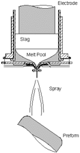
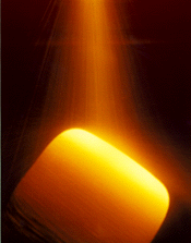
| Figure 1. The clean-metal spray forming process: (a) a schematic of the process; (b) spray forming. | |
Spray forming can compete economically with existing cast and wrought technologies if the resulting geometric shape is near-net, resulting in substantially less material loss during subsequent processing as compared to conventional routes. This is not the approach taken in the work reported here, but it is an area of active research by other researchers.4
Spray forming can also compete with powder processing for billet-making because of the reduced number of processing steps and increased yield. In the past, this possibility has not been exploited as a cost-effective alternative for superalloys to be used in critical fatigue-limited applications because of the lack of a primary oxide-removing process. It is a solution to this problem that led to the CMSF process.
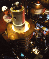
CMSF has the potential for producing P/M equivalent alloys at low cost. The process, shown in Figure 1, combines two conventional processes—ESR and spray forming—using an all-copper, inductively coupled, water-cooled guide system referred to as the cold-walled induction guide (Figure 2). The ESR process refines incoming material, eliminating ceramic inclusions upon melting of the input ingot. The cold-walled induction guide transfers the refined liquid metal to the spray-forming system and assures that no ceramic inclusions are reintroduced when the liquid is poured from the crucible, as would otherwise occur with conventional ceramic nozzles.
The CMSF approach replaces the mechanical removal of oxides (sieving) performed in P/M with a more reliable thermochemical reaction in the ESR furnace; hence, the yield loss associated with sieving is reduced. The new process requires no ceramic furnace liners or transfer nozzles and, thus, assures a clean superalloy for critical rotating applications.
 |
 |
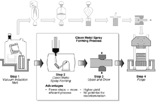
| Figure 2. The input ingot is lowered into the inductively coupled, water-cooled guide system—the cold-walled induction guide. | Figure 3. The CMSF processing sequence. |
After isothermal forging, the workpiece is ultrasonically inspected, heat treated, and machined in the shape of a disk. The reduced number of processing steps as compared to the P/M processing route, the higher yield, and the use of conventional forging presses in conversion results in a net reduction in cost of the resulting forging billet.
In addition to the technical benefits, several economic benefits can be expected.
| Table I. 718 Electron-Beam Button Cleanliness Data | |||||
|---|---|---|---|---|---|
| Material Source | Total Number of Oxides | Total Oxide Area (mil2) | Button Weight (g) | Specific Oxide Area (mm2/kg) | Major EDX Peaks |
| VIM Bottom | — | 414.9* | 610.2 | 0.439 | Al/O |
| — | 140.0* | 611.1 | 0.148 | Al/Mg/O | |
| — | 278.3* | 581.1 | 0.309 | Al/Mg/O | |
| Standard Triple Melt | 0 | 0 | 537.3 | 0.000 | — |
| 0 | 0 | 522.3 | 0.000 | — | |
| 23 | 8.6 | 499.6 | 0.049 | Not Measured | |
| VIM/ESR/VAR | 2 | 0.7 | 561.3 | 0.001 | Not Measured |
| 0 | 0 | 527.3 | 0.000 | — | |
| 0 | 0 | 553.0 | 0.000 | — | |
| High-Rate ESR Top | 19 | 20.9 | 540.4 | 0.025 | Not Measured |
| 14 | 12.6 | 511.3 | 0.016 | Not Measured | |
| 55 | 49.9 | 501.1 | 0.064 | Not Measured | |
| High-Rate ESR Bottom | 62 | 86.2 | 509.6 | 0.109 | Not Measured |
| 89 | 89.9 | 509.3 | 0.114 | Not Measured | |
| 63 | 78.1 | 503.4 | 0.1 | Not Measured | |
| CMSF Top | 0 | 0 | 649.5 | 0 | — |
| 1 | 0.02 | 683.6 | ~0 | — | |
| 0 | 0 | 676.7 | 0 | — | |
| 0 | 0 | 660.5 | 0 | — | |
| 0 | 0 | 654.3 | 0 | — | |
| *Oxide agglomerate | |||||
The EB button test specimens for the CMSF data were taken from a preform that was sprayed using nitrogen gas; a nitride raft formed at the top of all buttons. Metallography was performed on cross sections taken from some of the buttons to determine if the observed nitride raft obscured oxides; no hidden oxides were found. EB buttons taken from conventionally melted, nitrogen-atomized preforms show large numbers of oxides and high specific oxide areas despite the presence of the nitride raft.
| Table II. Results of Rapid-Strain-Rate Hot-Tensile Test As-Sprayed Alloy 718* | |||
|---|---|---|---|
| Temperature (°C) | Ultimate Tensile Strength (MPa) | Elongation (%) | Reduction in Area (%) |
| 871 | 392.4 | 5.8 | 3.1 |
| 461.4 | 42.2 | 48.4 | |
| 927 | 305.5 | 69.3 | 58.8 |
| 271.7 | 10.8 | 16.0 | |
| 982 | 195.8 | 22.7 | 17.0 |
| 238.6 | 38.2 | 42.8 | |
| 1,038 | 155.8 | 86.4 | 78.4 |
| 153.1 | 95.3 | 81.7 | |
| 1,093 | 113.1 | 100.1 | 82.7 |
| 111.7 | 72.9 | 74.6 | |
| *Test bars were cut from the center location and oriented parallel to the preform longitudinal axis. All tests were performed on the as-sprayed material. | |||
Rapid-strain-rate elevated-temperature tensile properties were obtained to evaluate the hot ductility characteristics of the material between 871°C and 1,093°C. Both the strength and ductility exhibit significant variability below 982°C (Table II), possibly related to porosity, but appear to be adequate for hot workability.
References
1. R.L. Kennedy et al., "Superalloys Made by Conventional Vacuum Melting and a Novel Spray Forming Process," 13th International Vacuum Congress, editor/s (City: Publisher, 1995), pages.
2. A.G. Leatham and A. Lawley, "The Osprey Process: Principles and Applications," Int. J. of Powder Met., 29 (4) (1993), pp. 321–329.
3. P.S. Grant, "Spray Forming," Progress in Materials Science, 29 (1995), pp. 497–545.
4. T. Tom and K. Bowen, "SprayCast-X for Aerospace Applications," Third Int. Conf. on Adv. Materials and Processing, editor/s (City: Publisher, 1998), pp. 1681–1686.
5. H.C. Fiedler, T.F. Sawyer, and R.W. Kopp, "Spray Forming—An Evaluation Using IN718," Proc. of the 1986 Vacuum Metallurgy Conference on Specialty Metals Melting and Processing, editor/s (City: Publisher, 1986), pp. 157–165.
6. H.C. Fiedler et al., "The Spray Forming of Superalloys," J. of Metals, 39 (8) (1987), pp. 28–33.
7. J.M. Moyer et al., "Advances in Triple Melting Superalloys 718, 706 and 625," Superalloys 718, 625, 706 and Various Derivatives, ed. E.A. Loria (Warrendale, PA: TMS, 1994), pp. 39–48.
ABOUT THE AUTHORS
W.T. Carter, Jr., M.G. Benz, A.K. Basu, R.J. Zabala, and B.A. Knudsen are with General Electric Corporate Research and Development.
R.M. Forbes Jones, H.E. Lippard, and R.L. Kennedy are with Allvac, a division of Allegheny Teledyne Industries.
Direct questions about this or any other JOM page to jom@tms.org.
| Search | TMS Document Center | Subscriptions | Other Hypertext Articles | JOM | TMS OnLine |
|---|