 |
The following article is a component of the April 1999 (vol. 51, no. 4) JOM and is presented as JOM-e. Such articles appear exclusively on the web and do not have print equivalents.
|
Spray Forming: Overview
Spray Forming: Alloys, Products, and Markets
Alan Leatham
 |
|---|
| CONTENTS |
|---|
|
Spray forming offers a combination of low-cost manufacturing with enhanced properties and performance. As such, it has emerged as a key competitor for existing technologies, such as casting, ingot metallurgy, electrode remelting processes, and powder metallurgy. This article provides a brief overview of the commercial status of spray-forming technology and markets.
The Osprey ProcessTM offers a unique combination of low-cost manufacturing with enhanced properties and performance and, as process scale-up proceeds, is becoming established as a major metal-forming process competing with and gradually taking markets from the existing technologies of casting, ingot metallurgy, electrode remelting processes, and powder metallurgy (P/M). The cost benefit derives from the single-step operation of converting molten alloy directly into a semifinished product. The property benefits arise from rapid solidification, which promotes microstructural refinement and eliminates macrosegregation.
The range of products currently being manufactured covers a broad spectrum of shapes, alloys, and markets, including round billets, tubes, rings, and clad products; aluminum-, copper-, nickel-, iron-, and silicon-based alloys; and automotive, electronic, aerospace, and general engineering components. Currently, the main applications for spray forming are
- Aluminum-alloy billets. Installed manufacturing capacity is 3,500 t/y at Peak (Germany), 1,000 t/y at Sumitomo Light Metals (Japan), and 400 t/y at Osprey Metals (United Kingdom). Peak is manufacturing Al/Si alloy billets for subsequent conversion into cylinder liners for use in automotive engines.1 More specialist, high-strength (Al/Zn), high-temperature (Al/Cu), and light-weight alloys (Al/Li) and metal-matrix composites (MMCs) are produced at Osprey Metals,2 mainly in conjunction with Peak. Kobelco has also recently announced the commercialization of special aluminum alloys for use as sputter target materials.
- Copper-alloy billets. The combined manufacturing capacity at Swissmetall Boillat (Switzerland) and Wieland (Germany) is in excess of 2,000 t/y, but presently only part of this capacity is being utilized. One of the main products for which there is considerable growth potential is electronic connectors, particularly for use in "high-tech" telecommunication applications.3 Spray-formed connectors produced by Swissmetall are already starting to replace wrought Cu-Be alloys and P/M Cu-Ni-Sn alloys.
- Special steel and superalloy billets. A new plant recently installed at Danspray (a subsidiary of Danish Steel, Denmark) for high-alloy steels has a single-shift capacity of 2,000 t/y and will be used for producing both ingot-metallurgy alloys, such as D2 tool steel, and P/M-type alloys, such as T15 high-speed steel.4 Superalloy billets are presently manufactured in a pilot plant at Osprey Metals for evaluation by Allvac SMP (United Kingdom).5 A pilot facility6 for producing billets from a refractory-free melt source is under development at General Electric (United States) in conjunction with Allvac (United States) for turbine discs applications.
- Superalloy rings. Rings, seals, and cases for use predominantly in aircraft gas-turbine engines are being manufactured by Sprayform Technologies International (a Howmet/Pratt and Whitney joint venture company). A new plant recently installed at Sprayform Technologies (United States) has a manufacturing capacity of 500 t/y (single shift) using a three-tonne vacuum-induction melting (VIM) furnace.7
- Stainless steel and nickel-alloy tubes and composite tubes. Sandvik Steel (Sweden) operates a plant with a capacity of approximately 750 t/y (two shifts), where one of the main products is composite tubing for use in municipal waste incinerator plants.8
- Rolls and clad rolls. Small-section mill rolls continue to be spray formed by Sumitomo Heavy Industries Foundry and Forgings (Japan). Clad rolls, which are produced on a development basis only at Osprey Metals, are being evaluated at Sheffield Forgemaster Rolls (United Kingdom).9
- Silicon-aluminum alloys. A unique series of alloys are being produced by Osprey Metals for use in electronic packages, heat sinks, and other applications where lightweight materials with a low coefficient of expansion are a requirement.10
 |
 |
| a | b |
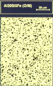
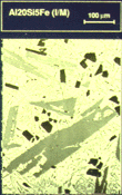
| Figure 1. An Al-20Si-5Fe alloy (a) spray formed and (b) cast. |
A more comprehensive review of the technology will be given at the Fourth International Conference on Spray Forming, which will be held in Baltimore, Maryland, on September 13–15, 1999. Topics at the conference will include lightweight and copper alloys, superalloys and other high-temperature materials, the U.S. Defense Advanced Research Project Agency's low-cost spray-form program, special steels, electronic packing and heat-sink materials, clad products, rolls, fundamentals and modeling studies, reactive alloys, metal-matrix composites, and thixoformed products.
Due to the single-step processing cycle, spray-formed aluminum alloys can be produced at substantially lower costs than P/M products, approaching cost levels of direct chill (DC) cast alloys at high production volumes. Moreover, critical properties such as fatigue life and fracture toughness are often improved as compared to P/M, mainly as a result of the absence of oxide contamination. While the properties of conventional DC cast alloys have also been demonstrated to be significantly enhanced by spray forming as a result of microstructural refinement, it is the ability to produce alloys not possible by ingot routes where the most dramatic improvements can be gained.2
Hypereutectic Al-Si alloys exhibit refined silicon particles on the order of 3–5 µm in the as-sprayed condition as compared to hypereutectic alloys produced by casting, where primary silicon particles are much larger, often approaching 100 µm in size or more (Figure 1). The refined silicon particles allow the spray-formed alloys to be more readily machined, and the wear resistance is excellent. One variant of the alloy is currently being used on a large scale for automotive-engine cylinder liners by Mercedes Benz. The nominal composition and properties of another commercially available alloy is shown in Table I.
| Table I. Properties of Spray-Formed Aluminum Alloys |
|---|
| Alloy |
Tensile Strength (MPa) |
Yield Strength (MPa) |
Elongation (%) |
Density (g/cm3) |
Modulus (GPa) |
CTE (10–6/K) |
| Al-20Si-5Fe-2Ni (4XXX) |
360 |
240 |
2 |
2.78 |
98 |
16 |
| Al-11.5Zn-2.5Mg-1Cu-0.2Zr (7XXX) |
705 |
688 |
13 |
2.88 |
74 |
21 |
| Al-4Li-0.2Zr (8XXX) |
528 |
459 |
4.7 |
2.41 |
84 |
21.6 |
Al-Zn-Mg-Cu alloys have traditionally been the highest strength alloys, but further increases in strength are restricted by the occurrence of macrosegregation in large ingots as well as difficulties in ingot casting when solute contents become too high. Spray forming overcomes these problems, and 7XXX alloys exhibiting the highest strength levels of wrought aluminum products with excellent fracture toughness and high cycle fatigue properties are being manufactured. The nominal composition and properties of one alloy that is currently registered with the Aluminum Association is shown in Table I. The high strengths enable the replacement of conventional alloys such as 7075, as well as titanium and steels, in some cases. Potential applications include aerospace components and sports-related automotive products, such as axle carriers, racing wheels, and connecting rods for high-performance engines.
 |
 |
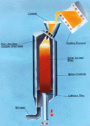
| Figure 2. The Osprey vertical billet process. |
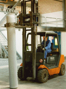
Figure 3. An Al/Si spray-formed billet (300 mm diameter x 2.5 m long) (courtesy of Peak). |
One limitation to conventional Al-Li alloys is the anisotropy exhibited by products manufactured from ingot-metallurgy source material. Through the refined grain structure produced by spray forming, Al-Li alloys with improved isotropy have been demonstrated. In addition, the Osprey process enables higher lithium contents to be added to the alloy without the problems of ingot cracking and macrosegregation that occur in ingot casting. Specifically, a binary alloy with nominally 4 wt.% lithium has been developed with densities as low as 2.4 g/cm3 and with specific stiffness levels more than 30 percent higher than conventional aluminum alloys (Table I). With moderate strength and good corrosion resistance, this ultralight alloy is suitable for applications where low weight and specific stiffness are paramount, including space and aircraft parts as well as high-performance automotive wheels.
Al-Cu-Mg-X alloys with improved elevated temperature strength coupled with good wear resistance in comparison to conventionally cast alloys have been demonstrated. Spray forming enables an increased level of fine dispersoid particles to be incorporated into the alloys without the occurrence of coarse primary particles that are often seen if high alloy contents are produced by ingot casting. These materials have been examined for elevated-temperature aircraft components as well as selected automotive applications, such as pistons, especially in racing applications. Alloys with further improvements in high-temperature properties are under development at Pennsylvania State University11 utilizing the rapid solidification inherent in spray forming to produce materials with a high content of aluminum intermetallics.
MMCs, in which the matrices are reinforced with ceramic particles up to 15% by volume, have been spray formed. These MMCs exhibit greatly increased stiffness and wear resistance with little cost penalty.
As an example of the potential for large-scale manufacturing by spray forming, Peak is currently producing more than 3,000 t/y of hypereutectic Al-Si alloy in three plants in Europe.1 All three plants operate on the vertical billet plant principle (Figure 2), with the most recent, state-of-the-art facility being designed for spray forming billets up to 2.5 m long x 150–400 mm diameter (Figure 3). Typically, 20 such billets are produced over three shifts. Allowing for plant utilization, output from the plant is currently running at a level of 1,500 t/y, but this figure is expected to increase in the near future. In order to minimize operating costs, nitrogen atomizing gas is taken directly from a pipeline. Deposition rates are maximized by using a twin-atomizing system, which operates at metal flow rates of approximately 15 kg/min.
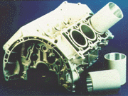 |
| Figure 4. A high-pressure diecast engine block with spray-formed Al/Si cylinder liners (courtesy of Peak and Daimler-Benz). |
The major application for the Al/Si alloy is in the manufacture of cylinder liners for use in Daimler-Benz automotive engines, although other car manufacturers are expected to take up the technology in the near future. The alloy used for the liners is Al-25Si-4Cu-Mg (wt.%) and has been specifically developed by Peak to provide the required properties and performance levels. The manufacturing cycle for the cylinder liners includes spray forming, seamless tube extrusion, rotary swaging, and sectioning into liners. The engine block is then high-pressure diecast around the liners (Figure 4). The liners, which are being used to replace a cast product (i.e., gray cast iron) in aluminum engine blocks, offer several significant advantages over the conventional product, including a reduction in engine weight, reduced oil consumption and hydrocarbon (HC) emissions (up to 30% less), increased engine power and efficiency, reduced friction and piston wear, reduced noise, and good machinability and ease of recycling.
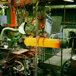
Copper-alloy billets are spray formed in vertical billet plants of similar design to those used for aluminum alloys (Figure 3), with billets up to 2.5 m in length being produced (Figure 5). Spraying rates, however, are typically in the range 30–60 kg/min. The billets are subsequently fabricated by conventional extrusion and drawing or rolling to produce thin rods and wires or thin, narrow strip. Swissmetall Boillat has been actively involved in commercializing such products for use in "high-tech" connectors, especially for applications in telecommunications, such as mobile phones.3
According to Swissmetall Boillat, there was a requirement in the market for new materials with a more favorable price/performance ratio, very high mechanical properties to meet the ever increasing demands of miniaturization, and improved thermal relaxation properties at higher operating temperatures. Accordingly, Swissmetall Boillat has developed and commercialized four spray-formed copper alloys (which could not be fabricated by ingot metallurgy due to excessive macrosegregation) which meet these requirements and, in particular, offer a low-cost option to expensive ingot-metallurgy Cu/Be and P/M Cu/Ni/Sn.
Two new, machinable alloys are available in rod form up to 5 mm in diameter. One alloy (PS2) is a brass-containing Cu-16Zn-2Si-1Pb, and the other (BO5) is a bronze of composition Cu-13.5Sn-0.5Pb. Both alloys have high machinability indexes of 90% and 80%, respectively (compared to standard Cu-39Zn-3Pb, which is 100%), and therefore, tool wear is low with small chip generation—a prerequisite in the automated machining of small connector components. The properties of the alloys (Table II) are achieved by drawing only; thermal aging is not required as the alloys are nonheat-treatable.
| Table II. The Typical Properties of Spray-Formed, Free-Machining Copper Alloy Rods (up to 5 mm diameter) |
|---|
| Alloy |
Modulus of Elasticity, E (kN/mm2) |
Yield Strength, Rp0.2 (N/mm2) |
Tensile Strength, Rm (N/mm2) |
Elongation, A (%) |
Hardness HV |
| B05-Hard |
85 |
800 |
900 |
5 |
240 |
| B05-Spring Hard |
85 |
900 |
1,000 |
1 |
260 |
| PS2-Hard |
105 |
800 |
950 |
1 |
250 |
The BO5 alloy is particularly interesting because in the hard-quality condition it possesses a reasonable level of elongation (approximately 5%), which can provide the possibility of subsequent cold deformation. In addition, the alloy exhibits a high yield strength in combination with a low modulus of elasticity, which uniquely permits very large elastic deformation (more than 1%). In the case of plugging two connectors together, this has the advantage of permitting a larger misalignment without plastic deformation and, consequently, without risking a loss of mechanical properties. In addition, in the case of connectors with many pins, this can minimize the insertion forces during plugging. With respect to thermal stress relaxation, both BO5 and PS2 alloys have usable properties up to 125°C and 150°C, respectively.
Two alloys have been commercialized in the form of wires and thin strip. One alloy is a new composition—Cu-13.5Sn (B14)—and the other alloy is a reincarnation of a well known but expensive P/M alloy, Cu-15Ni-8Sn (CN8), which can now be produced at lower costs by spray forming. The properties of both alloys are achieved by cold deformation, followed by aging in the case of the CN8 alloy. One of the advantages of CN8 is that it suffers only minimal distortion during heat treatment as compared to conventional Cu/Be alloys, which are prone to substantial distortion. Both the CN8 and the B14 alloys exhibit high mechanical properties in terms of modulus and yield strength, with tensile strengths in the range of 1,100–1,400 N/mm2. Furthermore, CN8 has exceptional resistance to thermal relaxation and is superior to Cu/Be (Table III).
| Table III. A Comparison of the Thermal Stress Relaxation Properties of Spray-Formed CN8 Alloy with Wrought Cu/Be* |
|
CN8 Remaining Stress (%) |
|
CuBe2 Remaining Stress (%) |
| Time (h) |
175°C |
200°C |
260°C |
|
175°C |
200°C |
260°C |
| 10 |
97 |
92 |
92 |
|
87 |
76 |
<70 |
| 100 |
95 |
87 |
87 |
|
84 |
70 |
<70 |
| 1,000 |
93 |
83 |
77 |
|
80 |
<70 |
<70 |
| *Initial stress level = 75% of YS. |
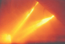
Currently, large-diameter billets in both special steels and superalloys are spray formed in a horizontal pilot plant operated by Osprey Metals. The plant, which has a melt capacity of 1.2 tonnes and can produce billets up to 1.2 m long x 400 mm diameter (Figure 6), has been developed in conjunction with Danspray4 and Allvac SMP5 with funding from the European coal and steel community. As a result of this successful development, Danspray is commissioning a larger production plant based on a four-tonne melt furnace linked to a vertical spray chamber (Figure 3) for manufacturing special steel billets up to 2.4 m long x 500 mm diameter. Both plants use twin-atomizer technology (Figure 7), which, compared to the use of a single atomizer, permits deposition rates to be increased (up to 100%), nitrogen gas consumption to be lowered (by approximately 25%), deposition yield to be improved (e.g., from 70% to 90%), and billet diameter to be increased (e.g., from 200 mm to 400 mm).
Typical processing conditions for D2 tool steel are 55 kg/min. atomizing rate and 0.75 m3/kg nitrogen consumption with a 90% deposition yield for a 400 mm diameter billet. This means a total spraying time of 50 minutes for a 2.4 m long x 400 mm diameter billet (i.e., 24 tonnes), with the possibility of direct hot working after a short time in a soaking furnace. Danspray's plant will be operated on a batch basis with a potential triple-shift capacity of approximately 6,000 t/y.
 |
 |
 |
 |
| Figure 5. A vertical 2.5 m long spray-formed copper alloy billet (courtesy of Swissmetall Boillat). |
Figure 6. A spray-formed special steel billet (400 mm diameter x 1 m) (courtesy of Danspray and Allvac SMP). |
Figure 7. Steel billet being horizontally spray formed by twin atomization. |
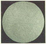
Figure 8. The macrostructure through a 400 mm diameter slice of D2 tool steel. |
The development of continuous spray forming plants by withdrawing the billet from the base of the spray chamber and in-line cutting (e.g., similar to conventional continuous casting) is now being considered by Osprey Metals and Mannesmann Demag Technica for steel and other alloy systems. Alternatively, using existing technology, two spray chambers could be used with a continuous supply of molten alloy that would be switched alternately between the two chambers. Such plants would be capable of producing up to 13,000 t/y of steel billets. A third possibility is to operate multiple spray chambers simultaneously, which although not truly continuous, would remove the need to hold large batches of molten alloy for prolonged periods of time.
At present, the main interest in spray forming iron and nickel-based alloys is with existing alloys, where spray forming provides the opportunity to lower costs and/or to improve properties. Consequently, very little work has been carried out on the development of new alloy compositions, although this could be a fruitful area for future research at a research institute. The existing categories of alloys which have been spray formed include wrought steels that cannot be continuously cast and are produced by casting into an ingot mold, steels and superalloys that are processed by double melt, consumable electrode remelting technology, and P/M steels and superalloys.
To illustrate some of the features of spray-formed special steels, a macroslice is shown in Figure 8 taken through a 400 mm diameter spray-formed and annealed billet of D2 (1.5C-12Cr-1Mo-1V), which shows a uniform and dense macrostructure with freedom from macrosegregation. Following forging, the carbides can be seen to be fine and uniformly distributed, which is in contrast to the coarser, segregated carbides present in conventional ingot-cast and forged D2 and electrode remelted alloy. A range of products (e.g., Sendzimir rolls and powder compaction tools) manufactured from the spray-formed D2 have been extensively field tested with promising results.
 |
 |
| a |
b |
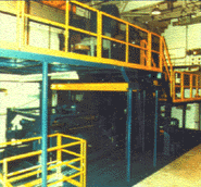
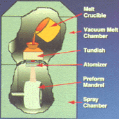
| Figure 9. (a) A Spraycast-X furnace and (b) schematic of Sprayform Technologies' Spraycast-X process. |
 |
 |
| a |
b |
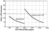
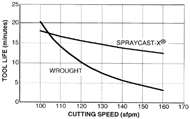
| Figure 10. A machinability study on Udimet 720 showing Spraycast-X versus cast and wrought alloy at (a) 0.010 in. depth of cut and (b) 0.040 in. depth of cut. |
Spray forming also compares favorably to P/M for many alloys, except that processing costs are much lower. P/M grade superalloy billets are particularly amenable to spray forming and exhibit freedom from macrosegregation, excellent forgeability, and fine microstructures. High-speed steels, such as T15, can also be manufactured with microstructures and properties similar to the equivalent P/M alloys. However, certain grades of high-speed steel have proved challenging to spray form (such as those which contain low levels of primary carbide formers), and fine carbide microstructures can sometimes be difficult to generate without compositional changes.
In 1997, Howmet and Pratt and Whitney formed a joint venture company, Sprayform Technologies International, with the prime objective of marketing and commercializing spray-formed rings and cases for aircraft gas turbines made by a modified Osprey process (Spraycast-X®). Sprayform Technologies currently operates two spray-forming facilities.7 A recently upgraded plant based on a 400 kg vacuum-melting furnace is used to spray form superalloy rings up to 760 mm diameter x 400 mm long x 75 mm thick. Atomizing rates are typically 35–45 kg/min., and deposition yields are about 80%. The metal is deposited onto a low-cost, pre-shaped, and pre-heated mild steel mandrel that rotates and traverses under the spray to produce the desired shape of ring preform (Figure 9). The plant has a capacity of approximately 250 t/y. A new, larger plant recently installed has a three-tonne VIM furnace and has been designed to produce rings up to 1,500 mm long x 1,400 mm diameter. Plant capacity is 500 t/y per shift. Both plants use argon as the atomizing gas to produce as-sprayed, pre-shaped rings with densities of about 98%. Normally these rings are then further processed by hot isostatic pressing (HIP) for static components or by HIP plus hot work for rotating parts.
Spray-formed rings and cases offer technical and economic advantages compared to cast, wrought, or P/M components. These include:
- Superior microstructures. Fine, uniform grain sizes (typically ASTM5-8) are generated in the spray-formed rings with no discernible macroscopic segregation. In addition, no coarse carbides or prior particle boundaries are evident, and oxygen contents are low.
- Variety of alloys. As a result of the desirable microstructures, cast, wrought, and high-strength P/M alloys can all be processed by spray forming. Experimental alloys can also be easily processed at relatively low cost.
- Improved hot-workability. Flow stress is reduced for wrought alloys (e.g., IN718) and even more so for high-strength, difficult-to-work alloys (e.g., Waspalloy®).
- Enhanced machinability. The fine, uniform structure and fine carbides result in markedly increased machining rates and tool life compared to the equivalent wrought alloys. For example, cutting speeds can be increased by 25–35% and tool life by up to two orders of magnitude (Figure 10).
- Equivalent or improved properties. Tensile, low-cycle fatigue, high-cycle fatigue, creep rupture properties, etc. are generally similar or better than the corresponding wrought alloy.
- High material utilization. The direct processing route to generate a near-net-shape results in a reduction of material usage, typically about 30% less than the wrought route.
- Shorter processing cycle. Delivery times can be shortened to weeks (e.g., 4–6 weeks) rather than many months, as is typical for VIM-VAR or VIM-ESR processed rings. This is made possible by the one-step process to manufacture a ring preform, in conjunction with the elimination or marked reduction in ring-rolling operations.
- Rapid and low-cost prototyping. The carbon-steel mandrels used as formers are either made by spin forming (for production runs) or hand fabricated by welding (for prototypes) and, therefore, are quick and inexpensive to make. Consequently, new rings (and/or alloys) can also be made extremely quickly at relatively low costs.
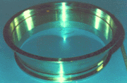
- Reduced cost. As a result of the benefits described, the main advantage of the Spraycast-X® process is the ability to manufacture high-quality ring and case components (Figure 11) at low cost (Table IV).
 |
 |
| Figure 11. A shaped and tapered Waspaloy Spraycast-X ring in the HIP + machined condition (courtesy of Howmet Corporation). |
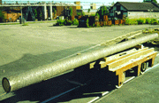
Figure 12. A 8 m long, low-alloy steel billet spray clad with nickel-based alloy (courtesy of Sandvik Steel). |
For several years, Sandvik Steel has been operating a 1.2 tonne melt capacity facility for spray forming stainless steel or nickel-based alloy tubular-shaped billets with lengths of 8 m, diameters up to 400 mm, and wall thicknesses in the range of 25–50 mm at spraying rates up to 80 kg/min. An important feature of the plant is a portable, bottom-pour, induction-heated ladle that is fitted with a pressure control and weighing system. Induction stirring and bottom pouring results in low contents of oxides and nonmetallic inclusions. The control of pressure above the melt and the weighing system permit precise control of the metal-flow rate into the atomizer, thereby enabling accurate dimensional control of the 8 m long tubular billets. In conjunction with other process parameters, manipulation of the atomizing gas flow rate ensures a uniform and macrosegregation-free microstructure along the full length. Using such a facility, Sandvik Steel is manufacturing two main products.
| Table IV. A Cost Comparison of Spraycast-X versus Cast and Wrought and P/M Products |
|
Cast and Wrought |
Spraycast-X |
P/M Process |
| Relative Raw Materials Usage (%) |
100 |
70 |
100 |
| Lead Time (weeks) |
12–16 |
2–4 |
12–16 |
| Labor (%) |
100 |
80 |
100 |
| Relative Finish Machining Costs (%) |
100 |
65–80 |
100 |
| Net Savings (%) |
— |
Up to 30 |
— |
The conventional route of tubemaking typically includes argon-oxygen decarburization (AOD) melting, continuous casting, hot rolling, boring, extrusion, and, for some applications, cold pilgering. This route is mainly used for the high volume production of tubes up to 250 mm diameter. However, in the case of large diameter or composite tubing, particularly in alloys which are prone to macrosegregation or are difficult or impossible to hot work, spray forming complements the conventional tubemaking process and also offers considerable flexibility in terms of tube diameter and wall thickness. The mechanical properties of as-sprayed tubes are often equivalent to conventionally cast and hot-worked material (e.g., 316 type stainless steel), but with several alloys, corrosion resistance is improved, possibly due to the finer microstructure arising from rapid solidification.
An interesting product for Sandvik Steel is the composite tubing manufactured by spray forming.8 The process route involves the deposition of a high-alloy steel or nickel-based alloy onto a carbon or low-alloy steel mandrel made by conventional means. The resulting composite billet (Figure 12) is subsequently cut, bored, machined, extruded, and cold pilgered. The high temperature and pressure involved in the extrusion operation generates a full metallurgical bond at the C-steel/high-alloy material interface. While such composite tubes can be manufactured by conventional technology, delivery times are relatively long, and the process is alloy-limited due to the difficulties of extruding materials with a high segregation tendency and/or high strain hardening during metal working.
One alloy that fits this category is a nickel-based alloy, Sanicro 63 (Ni-21Cr-8.5Mo-3.4Nb-3Fe). In the spray-formed condition, the alloy is of uniform microstructure and composition. These factors markedly improve the corrosion properties and hot workability of the alloy, which is now in use as the outer component of composite tubes in municipal waste incinerators. The use of C-steel as the inner component ensures an ideal combination of properties for such applications; namely, high strength on the inside of the tube for load-carrying properties and high-temperature corrosion resistance on the outside to protect against the flue gases. Typically, the patented composite tube product is used as a replacement for mono-alloy tubes in carbon or low-alloy ferritic steels or for refractory-protected or overlay-welded tubes. The C-steel tubes have a life in the incinerator of 6–24 months; whereas, the spray-formed composite tubes have a potential life of ten years, thus markedly reducing the extremely high costs of downtime for tube replacement.
 |
 |
| a |
b |
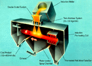
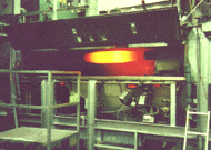
| Figure 13. (a) A schematic of the production of clad rolls and (b) a clad roll (courtesy of Forgemaster Rolls). |
Sumitomo Heavy Industries Foundry and Forgings has been manufacturing spray-formed rings in high-chromium cast irons and high-carbon, high-speed steels for several years. After downstream processing, the rings are fitted to a roll mandrel for use in round bar, flat bar, wire rod, and section mills. The main advantage offered by such products is a fine, carbide microstructure, which results in significantly longer roll lives (e.g., 2–4 times higher) compared to conventionally cast products. However, the rolls are currently spray formed as individual rings, which in combination with HIP to ensure full density, means that processing costs are relatively high. Consequently, in recent years, efforts have been made by Osprey Metals and others to scale up the technology by producing thick-walled tubes for subsequent slitting into rings and also by directly spray forming clad rolls with a metallurgical bond at the roll-arbor/clad-layer interface. In addition, the feasibility of hot forging such products to ensure full density has been investigated.
In particular, a project to assess the feasibility of spray forming clad hot and cold mill strip rolls has been carried out between Sheffield Forgemasters Rolls Ltd., Osprey Metals, and Sheffield University, with partial funding from the U.K. government. For this purpose, an existing plant at Osprey Metals was modified to include a 500 kg capacity melting furnace, a 600 kW induction heater for preheating the roll arbor, and twin atomizer technology to permit the deposition of thick layers of roll alloy as the hot arbor rotates and traverses under the spray in a single pass (Figure 13). Using this equipment, it was possible to produce sample rolls up to 400 mm diameter x 1 m long with clad thicknesses in the range 25–100 mm. Deposition rates were typically 50–100 kg/min., depending on alloy composition and roll size. Subsequently, the rolls were either tested in the as-sprayed or the hot-forged condition.
According to the results of the project,9 generally, under optimum conditions of pre-heat and deposition, high-integrity metallurgical bonds could be produced at the interface between a low-alloy steel arbor and the roll alloy, mainly for smaller diameter arbors (e.g., approximately 250 mm). However, larger diameters proved more difficult due to mechanical limitations on the plant, inefficient preheating, and poor atmosphere control, all of which resulted in prolonged heating times and oxidation at the interface.
A slight refinement in carbide microstructure is found in spray-clad, cold-roll alloys such as 0.8C/5Cr type, compared to conventional solid rolls made by casting and forging. However, dramatically finer microstructures are exhibited in hot-mill roll alloys such as 17CrIron (Fe-17Cr-2.6C-1Mo) or high-speed steel (Fe-8Cr-4V-2.5Mo-1.5C) compared to the conventional, spun-cast material.
| Table V. Toughness Data for High-Chromium Iron and High-Speed Steel |
| Material |
Energy (J/mm2) |
| High-Chromium Iron |
|
|
Spun Cast |
8.5 |
|
Spray Formed |
13.1 |
| High-Speed Steel |
|
|
Spun Cast |
9.0 |
|
Spray Formed |
16.2 |
Using a four-point bend test to assess toughness, Forgemaster Rolls found values more than 40% higher for spray-formed material compared to spun-cast (Table V). By quenching samples in iced brine up to repeatedly higher temperatures until cracking occurred, spray-formed high-chromium iron exhibited a higher thermal shock resistance of 400°C compared to 300°C for the equivalent spun-cast alloy. Using a 50 tonne hydraulic press, samples of spray-formed high-chromium iron were able to sustain 100% greater forging reduction than the spun-cast material at 900–960°C.
Under a standard wear test designed to simulate a rolling operation, spray-formed samples outperformed spun-cast by 5:1 and 3:1 for high-chromium iron and high-speed steel, respectively. At 600°C, the spray-cast high-speed steel outperformed the spun cast by 25%.
Spray-clad cold rolls (0.8C/5Cr) have been tested in a reversing narrow strip mill to evaluate the strength of the arbor/clad layer interface. Following arduous and extensive testing, no spalling occurred at the interface.
While the initial results on spray-clad conventional roll alloys have been encouraging, progress has been limited by the inherent deficiencies of the multipurpose development plant used for carrying out the project. For example, using the existing equipment, it was not possible to spray form a sufficiently large clad roll (with bonding) for testing in a hot mill. In addition, the potential for spray forming new alloy grades (not possible by the spun-cast route and where the greatest increase in roll performance can be expected) has not yet been evaluated.
In the case where cladding is not required, roll rings up to about 400 mm diameter have been spray formed in a CPM9V high-speed steel alloy. Initial results appear promising with microstructures similar to a P/M product; results of this investigation are to be reported at the forthcoming International Conference on Spray Forming.
A collaborative project between GEC Marconi Ltd. (United Kingdom), Alcatel Espace (France), TNO (Holland), and Osprey Metals, partly funded by the European Commission, has resulted in the development of a unique range of spray-formed Si/Al alloys with silicon contents up to 70% by weight.10 Such alloys cannot be successfully produced by ingot casting or P/M routes due to excessive embrittlement from coarse silicon precipitates or oxide contamination.
 |
 |
 |
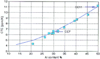
| Figure 14. The CTE of spray-formed Si/Al alloys as a function of aluminum content. |
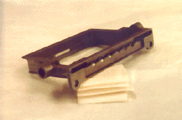
Figure 15. A channel amplifier housing (80 mm x 50 mm x 10 mm) in spray-formed Al-70Si (courtesy of Alcatel Telecom and GEC Marconi Ltd.). |
Figure 16. A power amplifier package (50 mm square) (courtesy of GEC Marconi Ltd.). |
The proportions of silicon and aluminum (Figure 14) can be varied to produce an alloy with a tailored coefficient of thermal expansion (CTE). Their low density, low CTE (stable over a wide temperature range), and high thermal conductivity make the SiAl alloys attractive for packaging microwave electronic circuitry and for heat sinks, particularly for applications in aerospace, satellites, defense, telecommunications, etc. where weight savings is vital. Conventional packaging alloys include Cu/W, Mo, Kovar, and Ti, all of which suffer from having either a high density and/or a low thermal conductivity. New, lightweight, low-CTE alloys include Be/BeO and Al/SiC composites. However, Be/BeO is expensive and toxic and the CTE increases with temperature fairly rapidly, while the Al/SiC is very difficult to machine and electroplate. The new Si/Al alloys do not have such problems. For example, the alloys can be machined with ease using carbide or polycrystalline diamond tooling. A typical component is shown in Figure 15. The alloys can also be nickel, gold, silver, or copper plated in preparation for attachment to housings, soldering to alumina circuit boards, and lid sealing. The component shown in Figure 16 is a package with conventional Kovar walls soldered to a base plate made from a spray-formed Si/Al alloy. Currently, three standard alloys are available (Table VI).
| Table VI. Commercially Available Spray-Formed Si/Al Alloys |
| Alloy |
CTE (ppm/K) |
Thermal Conductivity (W/m·K) |
Density (g/cm3) |
| Si-50Al |
10.5 |
140 |
2.5 |
| Si-40Al |
8.5 |
130 |
2.45 |
| Si-30Al |
6.5 |
120 |
2.4 |
One of the major advantages of spray forming is the ability to develop new alloys or products. These include new alloy compositions as a result of rapid solidification; MMCs formed by injecting particulate into the metal spray; in-situ reactive alloys created by creating a reaction between a constituent of the alloy to be sprayed and a constituent of either the atomizing gas or an injected particulate or by mixing sprays of different alloy compositions; thixoformed products by making use of the nondendritic microstructure of an as-sprayed alloy; and clad products by spraying various alloys onto different composition mandrels.
For these purposes and for carrying out fundamental studies, a network of R&D spray-forming plants has been established; notably at
U.S. Navy Labs,
Pennsylvania State University,
Applied Research Labs,
Advanced Institute of Science and Technology (Korea),
National Cheng Kung University (Taiwan),
IPEN (Brazil),
Oxford University Centre for Advanced Materials and Composites (United Kingdom),
Inner Mongolia Metals Institute (China),
Bremen University (Germany), and the
University of California at Irvine.
The author acknowledges the assistance of his colleagues at Osprey Metals and of Osprey's consultants Dr. Warren Hunt and Dr. David Jacobson in writing this paper and also Carol (Last Name) for the typing. In addition, the author thanks Osprey's licensees, particularly Peak, SLM, Swissmetall Boillat, Wieland, Danish Steel, Allvac SMP, Sprayform Technologies, General Electric, Allvac, Sandvik Steel, Sumitomo Heavy Industries Foundry and Forgings, Sheffield Forgemaster Rolls, and Kobelco for providing information included in this paper.
References
1. K. Hummert et al., "High Performance, Low Cost Aluminium Alloys Manufactured by Spray Forming," Proceedings of P/M Aluminium and Light Alloys for Automotive Applications Conf. (Princeton, NJ: MPIF, 1998).
2. Web site: http://www.ospreymetals.co.uk
3. J. Pierre Tardent et al., "New Copper Alloys for Electrical, Electronical and Mechanical Applications," Proc. of the Conf. Materialica, editor(s) (City: Publisher, year), pages.
4. C. Spiegelhauer, "Properties of Spray Formed Tool and High Speed Steels," The Third Pacific Rim Int. Conf. on Advanced Materials and Processing, ed. M.A. Imam et al. (Warrendale, PA: TMS, 1998), pp. 1653–1659.
5. L. Shaw and C. Spiegelhauer, "Spray Forming Large Diameter Special Steel Billets," Int. J. of P/M, 33 (3) (1997).
6. W. Carter et al., "Progress in Clean Metal Spray Forming," in Ref. 3, pp. 1675–1680.
7. T. Tom and K. Bowen; "Spraycast-X® for Aerospace Applications," in Ref. 3, pp. 1681–1686.
8. U. Forsberg et al., "Sandvik Sanicro 65 Composite Tube for Municipal Waste Incinerators," Proceedings of the 3rd Int. Conf. on Spray Forming, editor(s) (City: Publisher, year), pages.
9. R. Price and T. Gisborne, "High Quality Strip Mill Rolls—The Spray Way," Proc. of ROLLS 2000+ Conf., editor(s) (City: Sheffield Forgemasters Rolls Ltd., to be published).
10. M. Jacobsen and S. Sangha, "Future Trends in Materials for Lightweight Microwave Packaging," Microelectronics Int., 15 (3) (1998).
11. M. Amateau et al., "Properties of Spray Metal Formed Ultra-High Temperature Aluminium Alloys," 4th Int. Conf. on Spray Forming, editor(s) (City: Publisher, to be published).
ABOUT THE AUTHOR
Alan Leatham is sales and marketing director with Osprey Metals Ltd.
For more information, contact A.G. Leatham, Osprey Metals Ltd., Red Jacket Works, Millands, Neath SA11 1NJ, United Kingdom; telephone 44-1639-634121; fax 44-1639-630100; e-mail alan.leatham@ospreymetals.co.uk.
Copyright held by The Minerals, Metals & Materials Society, 1999
Direct questions about this or any other JOM page to jom@tms.org.


