 |
http://www.tms.org/pubs/journals/JOM/9909/Frazier/Frazier-9909.html
|
 |
http://www.tms.org/pubs/journals/JOM/9909/Frazier/Frazier-9909.html
|
 |
|---|
| TABLE OF CONTENTS |
Process design is a challenging endeavor involving difficult decisions, such as choosing the overall sequence of manufacturing operations, selecting the number of forming steps, and specifying the processing conditions. These decisions should be driven by the real need to achieve several possibly competing objectives associated with product specification, processing cost, and productivity. Software tools need to be developed that more directly assist in making design decisions, since designers generally have limited time for performing and interpreting detailed analyses.
Perhaps the most effective and direct means for dealing with modeling, optimization, and robustness issues is through a framework based upon dynamical systems principles1 and trajectory optimization.2 In this framework, a system is viewed as an interconnection of various interacting components, each being described by a set of continuous- or discrete-state equations (relations describing the time and spatial evolution of internal variables) and input-output relationships that when viewed as a whole provides a complete system description. The system is designed via the application of formal methods of constrained optimization, which require the designer to translate the design problem into mathematical expressions corresponding to constraints (needs) and objectives (wants). The choice optimization algorithm to obtain a solution is determined in part by the type and fidelity of the models as well as the objective of the particular design task.
A second issue is the choice of model order. Experience shows that the appropriate model order for a particular process design is highly dependent on the particular task at hand, whether it is developing a cost estimate for bidding, preliminary technical design, or final detailed design; time available for the design effort; or available computing resources. In general, model order should increase as the design progresses. Although this is a well-accepted axiom, what is less understood is that using too high an order at early design stages can be counterproductive as the increased complexity of high-order models, more often than not, introduces more design variables and more inferior local optima in the design space. Some of these optima are often associated with the numerical nature of the model and not the true problem. These local optima create havoc with the fast local search optimization algorithms that are suitable for use with high-order models, forcing the designer to use global optimization methods that require many simulations of the computationally expensive high-order models. If sufficient time and computing resources are available, this may be acceptable, but in most cases they are not. Of course, the disadvantage of using low-order models is that the resulting optimum, while global, is not likely to be the global optimum of the high-order model case; but it is hoped that it is closer to the high-order global optimum than would have been obtained using the high-order models from the outset given finite computing resources using local- or global-search methods. Fortunately, several researchers have become aware of these problems and are developing systematic methods for simultaneously managing model order and the search for the optimum in a single framework.3,4
 |
| Figure 1. A schematic of a hot-forging process. |
 |
| Figure 2. A sequence of dynamical processes. |
A typical systems representation for a metal-forging system is illustrated in Figure 1. Typical models for forging processes consist primarily of relations among workpiece material, tooling, and processing equipment. Two levels of coupling are present—models within models at the same time (instant) and models coupled sequentially through the workpiece (material) itself. In most cases, processes are not coupled directly, but are coupled only through the workpiece and its influence on the processes.
 (t) = fc(x(t),u(t))
in the continuous-time case or as
in discrete-time, where x and u are vectors of the system's state and control variables, respectively. The functions fc and fd define the relationships among the current state of the system, the current control variables, and the change of the state. The important point concerning dynamical models is that they are valid for a broad range of control signals, unlike algebraic models, which are only valid for a particular class of process controls, such as constant temperature and strain rate. The use of dynamical models provides greater predictive capability over algebraic models and provides more degrees of freedom in the time domain for optimal process design. Figure 2 illustrates a sequence of dynamical processes; each process is coupled to the next via the workpiece states.
 |
 |
| a | b |
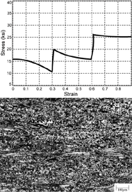
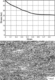
| Figure 3. A (a) strain-rate change test and (b) constant strain-rate test showing that different dynamical processing conditions can yield similar material microstructures. | |
 -TiAl alloy responds to different transient processing conditions. In this example, the material responses under constant strain-rate conditions versus increasing step changes in strain rate are compared. Because several different processing histories (trajectories) can lead to nearly the same end result, it is important to be able to find the best trajectory to realize the desired objectives. Consequently, models and design techniques for controlling microstructure during thermomechanical processing have been developed to address critical issues, such as stability, transient and steady-state response, and robustness of material trajectories, which are defined here as the time evolution of material attributes (phase, grain size, dislocation density, etc.).
Dynamical models of equipment systems are also useful, if not essential, for determining the desired adjustable parameter settings for coincident tracking of the equipment response with optimized commands. In general, furnaces, vacuum chambers, and forming machinery possess a range of time-varying performance capabilities that can be tuned to the needs of a given process. An example using a high-fidelity dynamical model of a 907 tonne forge press is described in Reference 5.
 |
subject to the constraints
ci(x(ti),u(ti))  0, i = 1 to Nc 0, i = 1 to Ncdi(x(t),u(t))  0, t 0, t [tl,tu]i, i = 1 to Nd [tl,tu]i, i = 1 to Nd |
and the material and process models
 |
w |
= f | w j |
(x | p j |
,xw,uj), j = 1 to Nf |
 |
p j |
= f | p j |
(x | p j |
,xw,uj), j = 1 to Nf |
where
| xwf | |||
| xp1 | u1 | ||
| x= |  |
and = |  |
| xpNf | uNf |
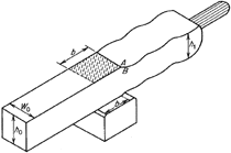 |
| Figure 4. An illustration of a cogging operation. |
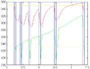 |
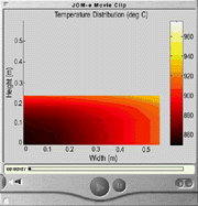
| Figure 5. A plot of the maximum and minimum billet temperatures throughout the process. The initial heat-up is not shown. |
 |
A diagram showing the processes and the possible physical design variables is given in Figure 8. Application of the optimization algorithm yielded an initial cost of $5,305 and a final cost of $1,191 for the first run and initial and final costs of $11,614 and $2,245, respectively, for the second run. The resulting process design is intended to determine the manufacturing sequence and process parameters to the first order. For example, in the forging processes, the volume of material required and the nominal shape of the forging dies are determined, but the exact shape of the dies is not. Detailed design, which should only impact cost at the second order, is still required to complete the process design.
 |
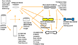 |
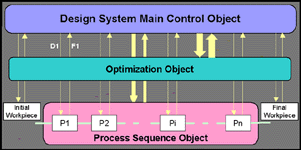
| Figure 7. The organizational structure of the design system. | Figure 8. The process routes and design parameters. |
The importance of considering dynamical effects in the design of thermomechanical materials processes cannot be overstated since these processes are inherently transient (time-varying) in nature. This design philosophy has been used very successfully by aerospace engineers for more than two decades to design flight trajectories and control parameters of multistage missiles, launch vehicles, and satellites. The design has also shown that the mathematical structure of the problem is precisely the same as multistage materials processes. Certainly the complexities of modeling the behavior of materials during processing, combined with an emphasis on the equilibrium behavior of material systems, have been a bane to the widespread use of dynamical systems engineering principles in materials and manufacturing processes design. However, the evidence of more materials and manufacturing researchers addressing these issues indicates that things are changing.
References
1. R.E. Skelton, Dynamic Systems Control (New York: John Wiley and Sons, 1988).
2. R.E. Stengel, Optimal Control and Estimation (New York: Dover, 1994).
3. N.M. Alexandrov et al., "A Trust Region Framework for Managing Use of Approximation Models in Optimization" (1998), pp. 16–23.
4. N.M. Alexandrov, "On Managing the Use of Surrogates in General Nonlinear Optimization and MDO," Proceedings of the 7th AIAA/USAF/NASA/ISSMO Symposium on Multidisciplinary Analysis and Optimization, AIAA paper AIAA-98-4798 (1998).
5. W.G. Frazier et. al., "Model and Simulation of Metal Forming Equipment." J. of Mat. Engineering and Performance, 6, pp. 153–160.
6. W.G. Frazier et al., "Application of Control Theory Principles to Optimisation of Grain Size during Hot Extrusion," Materials Science and Technology, 14 (1) (1998), pp. 25–31.
7. S. Jacobson (private communication).
W.G. Frazier is with the Air Force Research Laboratory, Wright-Patterson Air Force Base. E.A. Medina is with Austral Engineering and Software.
For more information, contact W.G. Frazier, Air Force Research Laboratory, WPAFB, Ohio; e-mail william.frazier@afrl.af.mil.
Direct questions about this or any other JOM page to jom@tms.org.
| Search | TMS Document Center | Subscriptions | Other Hypertext Articles | JOM | TMS OnLine |
|---|