 |
http://www.tms.org/pubs/journals/JOM/9909/Poindexter/Poindexter-9909.html
|
 |
http://www.tms.org/pubs/journals/JOM/9909/Poindexter/Poindexter-9909.html
|
 |
|---|
| TABLE OF CONTENTS |
Several Air Force Research Laboratory (AFRL) R&D initiatives are focusing on enhancing the functional relationship between critical design and engineering data and the tools that model the manufacturing fitness of a component. One such initiative is the Collaborative Optimization Environment (COE) program. Another initiative is the SAVE program, an open-systems architecture built on the common object request broker architecture (CORBA), which enables the seamless sharing of data across a wide array of commercially available modeling and simulation tools in support of systems design. The impact of such an integrated suite of simulation tools applied to the JSF is estimated to reduce system life-cycle costs from two percent to three percent.
The idea behind the application of integrated product and process development (IPPD) concepts is for a technology-development team to be able to balance the development of the processes required to realize the technology within acceptable cost and risk and within acceptable bounds of product performance. To be most effective, these multidiscipline teams demand a vastly improved generation of software modeling and simulation tools. For these tools to be effective, hybrid modeling across the different technical domains is critical. An example of hybrid modeling is the integration of systems engineering, design, engineering analysis, manufacturing, question and answer, support, etc. in a multifunctional, balanced team approach to product development.
Traditionally, the manufacturing disciplines have been at a distinct disadvantage in the IPPD process due to a lack of sophisticated tools and models needed to describe the emerging system from a manufacturing perspective. However, in the last five years with the advent of lower cost, more powerful networking and computing technologies, there has been an explosion in the use of modeling and simulation across the manufacturing enterprise, ranging from physics-based material development processes and fabrication and assembly activities to advance cost and life-cycle modeling and high-level business process representation. In the manufacturing domain, recently demonstrated advances in modeling and simulation tools offer the potential to efficiently examine the impacts of many manufacturing scenarios and, thereby, reduce risk before costly investments in tooling, materials, and facilities are made.
But even with these advances, the use of modeling and simulation technologies across the enterprise is far below that needed to fully understand and describe the system represented by the product and its associated processes. Modeling and simulation in manufacturing process applications are not considered to be critical-path activities, but rather are used as troubleshooting tools (reactive vs. proactive). Models of products and factory equipment and simulations of manufacturing processes are often created to help diagnose a problem, but are currently infrequently used to create and optimize process and product designs. The perception is that process modeling and simulation is expensive and time consuming; therefore, its use is limited to applications with a high return on investment.1
Another contributor to this perception is that the integration and interoperability of modeling and simulation tools is sorely lacking in the manufacturing realm. Most modeling and simulation tools are single-function. For example, they may deal with the stress and temperature profiles of products undergoing individual processes, but seldom do they deal with the total performance profiles of products and processes across multiple operations; even more rarely do they deal with interactive, real-time optimization of multiple product and process parameters. Attempts at improving the interoperability of process modeling and simulation tools are frustrated by grossly incomplete data representations as well as incompatible data structures and representation formats. Rich standards do not exist or are not widely used for representing and manipulating product designs and product and process parameters; no good standards exist to insure compatibility between process modeling and simulation tools and the rest of the systems that support any given manufacturer's product design and manufacturing environment.
The inability to exchange key product-design characteristics and analyze their impact on manufacturing can be seen in the following situation. An airborne weapon system experienced problems with wing flutter and stiffness, which impacted the handling and performance profile of the aircraft. When the production-development team discovered the problems, they were so far into system development that they could only propose two options. One option was to improve the actual structural stiffness of the aircraft by adding additional stiffeners to the wing. The second option was to improve the performance of the actuators connected to the wing structure to compensate for the flutter and provide tighter actuation control. The development team picked the second option to avoid increasing the weight of the aircraft. It is important to note that a full analysis of the impact of the first option was never performed to determine exactly how much the weight would increase. The inherent problems in deciding to improve the actuators were not completely discovered until five years into the decision cycle; at that point, not only did they discover manufacturing problems, but the design team realized they had locked in increased support costs for the aircraft. The decision to improve the actuators to meet the performance profile of the system either required more space in the wing structure for larger actuators and more hydraulics or additional boring operations to resize the actuator and increase performance. To enlarge the wing structure, the profile of the aircraft would need to be modified and would once again increase the weight. The decision was to bore out the actuators, but this affected the reliability of the components and led to major support and maintenance costs for the system. Later, it was discovered the change in the actuator also increased the power draw to the limits of the aircraft.
The capability to fully evaluate the end-to-end ramifications of the two original options does not currently exist. In the past, modeling and simulation initiatives have focused between two paradigms—design and manufacturing analysis and design and system performance. Effort must now be focused on making a full link in performance, design, manufacturability, and affordability.
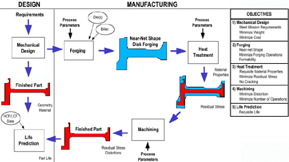 |
| Figure 1. The integrated disk design and manufacturing objective is to demonstrate geometry and finite element based MDO for complex product and process development. |
The cross-disciplinary communications are accomplished through the use of a multidisciplinary optimization language (MDOL).2 The MDOL is used to define the connections between commercial off-the-shelf and custom analysis packages. This language allows the software environment for specific processes to be extended and customized. The design parameters for a product can be tied to specific knowledge bases and programs that maximize the design parameters for the manufacturing processes that will produce them.
An example of the interdigitation method was used to optimize the process of roll forming a disk for a turbine-blade assembly. The objective of the roll forming was to produce a disk as close as possible to the near-net shape of the final disk form. The closer the disk is to final form, the greater the reduction in labor and costs to machine and finish the disk to its actual final form. Several problems arose in the manufacturing process as roll forming was used to finish the disk to near-net shape. After roll forming, the disk was machined and heat treated. During the heat-treating process, residual stresses were introduced into the disk, which caused warping and axial distortion as the disk cooled. It was discovered that the uneven cooling of the disk allowed the residual stresses to cause physical distortions.
Using the COE program, data were collected from the process; by tracking design variable history, a knowledge base was derived about the cooling characteristics of the features of the disk. Using this information, a customized finite-element analysis program was used to build a heat management profile. This profile analyzed cooling rates of different sections of the disk. By using the parameterized design features of the disk, a heat management plan was derived to control heat dissipation at each section of the disk (Figure 1).
The design variables were tied directly into the heat treating process used during the manufacture of the component. Using this capability, coordination between the design of the disk and manufacturing contraints were modeled to obtain the desired characteristics of the product. Cooling was uniformly distributed across the disk, and maximum stresses were reduced by 80 percent.
 |
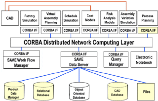
| Figure 2. The SAVE architecture. |
The SAVE WFM provides graphic process modeling and execution. It is implemented in java to provide full platform independence. The WFM software defines dependency relationships among the components of the process with decomposition down to the activity level. The query manager (QM) is a java application that provides the capability to browse, create, modify, and delete objects in the SDM. The SAVE QM does not interface directly with either the simulation tools or the WFM; its sole purpose is to provide access to information in the SDM through a mechanism other than the simulation tools within the SAVE tool suite.
Elements of the SAVE infrastructure are implemented as distributed CORBA objects to provide a flexible, expandable system that operates in a distributed, heterogeneous computing environment. Integrating a new virtual manufacturing code to operate within SAVE involves wrapping for infrastructure support and wrapping for data integration.
The supported simulation tool classes shown in Figure 2 are used to assess the cost, schedule, and risk of product and process design decisions. The SAVE system supports a range of manufacturing simulation classes, but is not dependent on the particular commercial tools chosen for use. Currently, tool classes (with SAVE demo tools hot linked) supported by SAVE include CAD, dimension and tolerance analysis, schedule simulation, assembly simulation, factory simulation, ergonomic simulation, risk modeling, and feature-based costing. Other tools can be substituted and new classes of simulation codes (within the manufacturing simulation domain) can be added by wrapping the code with a SAVE compliant interface to the infrastructure and data model server. SAVE architecture and I/O specification documents have been released into the public domain and are available on the web.4
 |
| Figure 3. The link to the SAVE data model. |
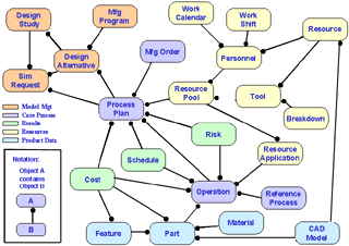
The top-level model in Figure 3 shows only the major interfaces (or classes) and their relationships with each other. The model contains five general categories of information necessary within the SAVE environment. Model-management data provide organization to the information stored in the SDM. One component of this data is the simulation request, which supplies the simulation tools with the necessary pointers to the SDM. The core-process data include process plans and operations within those plans; this is the primary set of data shared by the simulation tools. The resource data include tools, personnel, and work scheduling information applied to the operations in the process plan. Product data provide information about the part or assembly associated with the process plan, along with pointers to the associated geometric or computer-aided design data. Results data provide key decision-making information about the relative cost, schedule, and risk of the alternatives under consideration.
A typical manufacturing-simulation tool starts with the product definition and a process plan as an entry point and links to other relevant information from that interface. The top-level interfaces, including design study, design-study alternative, and manufacturing program, are more meaningful to the user in interpreting and managing the available information. The user, not one of the simulation tools, typically populates these items using the QM. Most other data elements in the model are used and/or populated by the simulation tool suite.
It is important to understand that the SDM does not attempt to supplant a product data management system nor to manage all of the data used or generated by the suite of manufacturing-simulation codes. Rather, the SDM is designed to contain and provide access to the information that is shared among tools. Growth of the SDM in the design feature area is a near-term area of interest for future research. The need to provide widely accepted definitions of intelligent design information in a readily accessible form to a wide range of CAx tools is a key driver for acceptance of the SAVE approach and rapid expansion beyond just manufacturing simulation.
 |
 |
| a | b |
References
1. R. Neal et al., 1998 Integrated Manufacturing Technology Roadmap for Modeling & Simulation—Fanout Review Draft (Oak Ridge, Tennessee: ORNL).
2. iSight, Technical Overview (Engineous Software).
3. SAVE Architecture & Tool I/O Specification, Release 3.0.
4. J.W. Poindexter and P.E. Cole, SAVE—Reducing Cost and Risk Through Virtual Manufacturing (Paper presented at the 85th Meeting of the AGARD Structures and Materials Panel, Aalborg, Denmark, 13-14 October 1997).
ABOUT THE AUTHORS
James W. Poindexter, Brian A. Stucke, and Gerald C. Shumaker are with the Materials and Manufacturing Directorate, Manufacturing Technology Division, Air Force Research Laboratory, Wright-Patterson Air Force Base.
For more information, contact J.W. Poindexter, Materials and Manufacturing Directorate, Manufacturing Technology Division, Air Force Research Laboratory, Wright-Patterson Air Force Base, 45433-7739.
Direct questions about this or any other JOM page to jom@tms.org.
| Search | TMS Document Center | Subscriptions | Other Hypertext Articles | JOM | TMS OnLine |
|---|