An Article from the April 2003JOM: A Hypertext-Enhanced Article
|
TMS
ONLINE | TMS
PUBLICATIONS | SITE
MAP An Article from the April 2003JOM: A Hypertext-Enhanced Article |
|
|
|
|
F.
Ojebuoboh is with Asarco,
Denver, Colorado, S. Wang is with Phelps
Dodge Corporation, El Paso, Texas, and M. Maccagni is R&D manager
at Engitec,
Novate Milanese, Italy.
|
Exploring traditional, innovative, and revolutionary issues in the minerals,
metals, and materials fields.
|
| OUR LATEST ISSUE |
|
Primary lead production is usually viewed in terms of two distinct operations:
converting lead concentrate to bullion and refining the bullion. Depending on
the nature of the concentrate, the bullion exiting the smelting furnace contains
a particularly broad range of impurities. For example, smelters of complex concentrates
may have iron, copper, nickel, cobalt, zinc, arsenic, antimony, tin, bismuth,
selenium, tellurium, silver, and gold, as well as sulfur and oxygen. Table
I shows a range of concentration for some of these impurities from operations
at the Asarco, East Helena
smelter blast furnace in Montana (operations are currently suspended at this
lead smelter). This attribute of lead bullion (i.e., excellent ability to dissolve
other elements) results in particularly complex refining as operations are introduced
to remove impurity elements originally associated with the concentrate, as well
as flux and furnace refractory. This article presents a new concept for refining
lead bullion, and unlike existing processes, it is robust enough that it does
not restrict impurity load in the bullion. The process has the potential of
achieving significant gains in hygiene, environmental controls, and efficiency
for the refining aspect of primary lead production. Also attractive about the
granulation-leaching-electrowinning process is that it could decouple the smelting
furnace from refining operations. A follow-up paper1
describes the flow-sheet development for winning the by-product metals, in particular,
the release of the precious metals sooner than conventional refining processes.
In conventional lead refining,2–4
the bullion from the smelting unit must invariably be drossed. Drossing (or
rough drossing) is accomplished by cooling the bullion to within 50°C of
the freezing point of lead. By crystallization, iron, copper, and many impurities
from the bullion are rejected in part or fully. A fine drossing process is conducted
where sulfur or, less commonly, phosphorus is used to scavenge residual copper
(to <15 ppm copper). For the most part, conventional lead refining—pyrorefining
(PR)—is conducted in gas-fired steel kettles in batch operations. However,
the Betts electrorefining process (BEP) produces a sizeable portion of commercial
lead estimated3 in a 1991
paper at 20% of total lead-refining capacity. In addition to drossing, BEP requires
partial PR to control certain impurities (antimony, arsenic, and bismuth) to
levels necessary to maintain anode integrity and slime adherence during electrorefining.
Thus, rough drossing and some softening of the bullion is required prior to
electro-refining. One BEP operation reported5
that anode composition is controlled to maintain Bi < 0.5%, and As + Sb <
1%. The choice of PR or BEP depends on factors that vary with a particular lead
producer, and a historical perspective regarding the role of bismuth in the
decision was provided in an earlier paper.6
Hygiene, environmental monitoring, byproduct constitution (or ability to control
raw material), and local energy costs are certainly factors that would be relevant
in a choice today between both options.
| |
||
| Element
|
Typical Wt.%
|
Range Wt.%
|
| Copper |
4.88 |
2.0–11.0 |
| Arsenic |
1.46 |
0.2–2.5 |
| Antimony |
2.78 |
1.0–3.0 |
| Silver | ||
| Sulfur | ||
| Tin | ||
| Bismuth | ||
| Zinc | ||
| Nickel | ||
| Tellurium | ||
| Lead | ||
| |
||
Granulation of lead bullion from the blast furnace, or any of the modern direct-smelting
furnaces (KIVCET and QSL), is a logical break prior to refining.
By decoupling the furnace operation, the break can be a tool to minimize impurity
variability, control refinery charge chemistry, and to reduce emissions from
primary lead production. Regarding the latter point, transfer pots between the
furnace and the drossing operations are a significant source of lead fumes to
perimeter monitors. The obstacles to granulating 360 t/d of furnace bullion
at the East Helena plant can be summarized by two key activities: (safely) quenching
a molten stream at 1,100 ºC–1,200 ºC and transporting flaky,
bulky, and interlocking granulated bullion.
A granulator was developed and built to overcome these obstacles. Figures 1a
and 1b are schematics of the device.
A refractory-lined steel reservoir between the settler spout and the granulator
is used to maintain discharge pressure into the water. The device consists of
the granulator hopper, a short conveyor belt at the base of the hopper, and
a bucket elevator to evacuate granulated bullion. An air jet at the bottom third
of the hopper could be used to maintain adequate water turbulence. Molten bullion
transfer is routinely done with bullion cars based on a rail system. For the
granulated bullion, a conveyor belt was found to be effective and the belt transport
also allowed dewatering to continue during transfer. Water consumption by the
granulation operation was estimated at 1,300 L/min. per tonne of bullion. Recirculation
of the granulation water was not addressed during development work; however,
a closed-loop circulation is preferred for reducing water consumption. The main
concern about recirculation is the build-up of metal content in the water. A
leach test was conducted to evaluate the effect of multiple contact of water
with bullion taken from the settler.
Lead, copper, and cadmium as shown in Table II were found
to increase with successive contact; arsenic, antimony, and silver showed no
increase.
| |
||||||
| No. of
Contacts |
Ag
|
Pb
|
Cu
|
As
|
Sb
|
Cd
|
| 0 |
|
|
||||
| 1 |
|
|
||||
| 2 |
|
|
||||
3 |
|
|
||||
4 |
|
|
||||
5 |
|
|
||||
6 |
|
|
||||
7 |
|
|
||||
8 |
|
|
||||
| * ND - not detected. |
||||||
East Helena smelter bullion (Table I) represents bullion that may be obtained from primary lead smelters treating complex concentrates. Granulation of this type of bullion must be conducted at temperatures greater than ≈ 870 ºC, a temperature that marks the incipience of the formation of molten speiss and molten matte. Otherwise, as the bullion cools below the threshold temperature, the following is likely to occur:
|
(1) |
Spontaneously, speiss(l) and matte(l) create fine dispersions within the lead bullion matrix. The transformation temperature for (1) is not precise, but quenching the bullion close to the discharge temperature (1,050°C–1,200°C) prevents speiss formation, which upon formation provides nucleation sites for further activity.
|
|
|
| a
|
 |
| b
Figure 1. A blast furnace bullion granulator showing (a) molten bullion path, (b) granulated bullion path. |
The Fluobor process was developed by Engitec Impianti (Milan, Italy) as an aqueous process for recovering lead from lead-acid battery metal scrap7 and directly from galena.8,9 Preliminary tests in 1993 by Marco Olper and his colleagues at Engitec Impianti demonstrated that the lead in granulated East Helena bullion could be selectively leached, purified, and electrowon with the Fluobor process (Engitec has since refined the process for direct refining of bullion and the modified process is trademarked LEADBOR). Applied to granulated bullion, Fluobor is an intrinsically simple aqueous process in which the bulk of the lead is dissolved as lead fluoborate. The dissolution mechanism is ferric, Fe3+, oxidation rather than fluoboric acid, HBF4, dissolution. The overall reaction is:
|
(2) |
The solution of lead fluoborate in iron fluoborate and fluoboric acid (HBF4) becomes the electrolyte from which lead is recovered by electrowinning. Similar reactions occur between ferric fluoborate and the impurity elements in the bullion (i.e., zinc, cadmium, antimony, arsenic, bismuth, copper, silver, etc.) albeit to varying degrees. Therefore, the solution from leaching must be purified by contact with lead granules in a cementation step. Zinc and cadmium, not amenable to removal by cementation, accumulate in the electrolyte over time and must be removed otherwise (e.g., by electrolyte bleed). Electrolytic deposition of lead occurs by the following reaction:
| (3a) |
| (3b) |
The counter reaction at the anode regenerates ferric fluoborate:
| (4a) |
| (4b) |
The regenerated ferric ion is returned to the leach step to dissolve lead by leaching new granulated bullion, thereby closing the loop.
| |
|
| a |
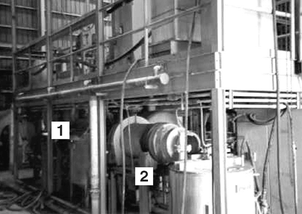 |
| b Figure 2. (a) A pilot plant for leaching and electrowinning lead (1) PLC system, (2) electrolytic cell, (3) filter press. (b) Pilot plant for leaching and electrowinning lead (1) leach tank, (2) cementation tank. |
A pilot plant was designed and built by Engitec
Impianti to demonstrate the leaching-electrowinning component of the process.
It had a design capacity of 45 kg/d of refined lead and consisted of two modules,
each covering 40 square meters. Figures 2a
and 2b show key components of the plant.
The modular arrangement permitted a two-level configuration necessary for the
cascade flow of electrolyte. As can be seen in Figure
2a, the plant included a programmable logic controller that could control
the key operations in the plant. These operations included regulating the amount
of granulated bullion introduced to the leach tank, leach tank mixing, cementation
tank mixing, and volume of anolyte and catholyte in the storage vessels. The
electrolytic cell and the filter press were housed on the top module. The plant
could be filled with 3,800 L of solution but was periodically operated at levels
as low as 3,000 L. The operational flow rate was nominally 220 L/h (1 gal/min.)
but operations could be maintained between 110 L/h and 450 L/h.
East Helena smelter bullion was used for all tests during operation of the pilot
plant, and granulated bullion composition was the same as that transferred to
the dross plant for plant production. Leaching was conducted in a 316 stainless
steel vessel with a working volume of 200 L. The vessel was horizontally mounted
and when activated, it rotated axially. This portion of the plant is shown in
Figure 2b. The leaching rate is driven
by the ferric-ion content in the return electrolyte, or more rigorously, the
ferric:ferrous ratio, Fe3+/Fe2+.
Leaching could be judged effective on the basis of two parameters: [Pb2+]
and [Fe3+]/[Fe2+].
For example, during the operation of the plant, the leachate always contained
the minimum required lead concentration of 100 g/L. The [Fe3+]/[Fe2+]
ratio varied from 0.05 to 0.45 and Fe3+ was
usually less than 4 g/L in the return electrolyte. Cementation was the primary
method of purifying the leach solution; thus, lead was used to displace the
impurity metals from solution. Initially, cementation was conducted with 3.2
kg/d of soft (pure) lead, and the process was maintained at 50°C. Observations
during the pilot program showed that ambient temperatures and a large loading
of granulated bullion, in lieu of soft lead, were sufficient to attain the same
level of purification as with soft lead.
The electrolytic portion of the Fluobor process is based on a divided cell configuration
where the cell is divided into strict anolyte and catholyte compartments. The
division is enforced with a diaphragm made from fine-mesh polyethylene separators
(W.R. Grace & Company
“Daramic”—Grace
divested its battery separation group in 1994 and it now goes by the name Daramic).
Lead was deposited on 316 stainless steel cathodes in two air-agitated catholyte
compartments. Four sheets of deposited lead could be harvested after a deposition
cycle of nominally 24 h. The anode was a graphite sheet (approximately 13 mm),
which was punched in a Swiss-cheese style to enhance anolyte flow. Electrowinning
was conducted under a fixed current of 500 A and a current density of 250 A/m2.
A schematic of the cell is shown in Figure
3.
|
|
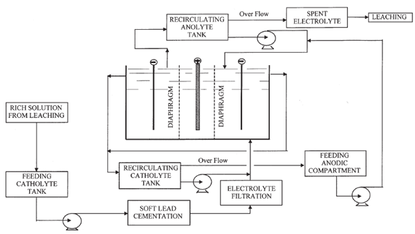
|
|
Figure 3. A schematic of the divided cell used in the electrowinning of lead with the electrolyte train (after Reference 9). |
One of the key attractions of this concept was the potential to release byproduct (silver and gold) metals rapidly. Data from over 70 deposition cycles were gathered during the operation of the pilot plant. A mass balance, Table III, made over input during the first 15 deposition cycles, provides an insight into accumulation of feed material. The imbalance, 5%, is primarily in process or accumulated material, an indication of the amount of material the plant maintains relative to raw material loading.
| |
||
| Units (kg)
|
|
% of Total Output
|
| Input |
|
|
| Granulated
bullion |
|
|
| Soft lead |
|
|
Total |
|
|
| |
||
Output |
|
|
Refined
lead |
|
|
Leach residue |
|
|
Cementation
residue |
|
|
Total |
|
|
|
|
||
Lead deposits were examined for their appearance, and cathode purity was determined by chemical analysis. Visual inspection of the deposits indicated that sheets were susceptible to dendritic growth (treeing), roughened surface, and excessive bonding to the cathode (steel substrate). After the first few tests, animal glue at 1 kg/100 kg lead was used to alleviate these problems. Assorted oils were periodically used to inhibit the growth of lead into the substrate so as to reduce the difficulty of stripping the cathode (This problem was not fully resolved and reappeared at different times during the plant operation). During stripping it was often evident a deposit was impure if it broke (i.e., brittle) because the impurities were likely to include arsenic and antimony. Cementation generated very fine, difficult-to-settle residue. Coagulation and settling of cementation residues was achieved with Percol l 727 (Allied Colloid Company) at a rate equivalent to 10 g/100 kg refined lead. With proper application of additives, the appearance of the lead sheets was flat and readily stripped. In Table IV, the chemical analyses of the deposits from tests 50 through 70 are presented. Impurity levels obtained by emission spectrograph and atomic-absorption spectroscopy determined the purity of the deposit. Many difficulties were encountered in the early effort through test 35 as attempts were made to correlate antimony and copper, and to a lesser extent, bismuth with their respective levels in the electrolyte. The inability to make this systematic correlation precluded attaining commercial-grade purity during most of the pilot tests. Silver, zinc, iron, and arsenic appeared to respond to solution purification by cementation from the initial tests. Antimony in tests 50–56 and in prior tests was determined to be in the range of 0.05% to 0.8% (500–8,000 ppm), whereas silver was typically less than 5 ppm.
|
|
 |
|
Figure 4. Unit operations in the direct electrolytic refining of lead bullion. |
To improve the purity of the refined lead (i.e., to control antimony, copper,
and bismuth), additional purification of the catholyte was required (test sequence
57–60 and test sequence 61–70). This was achieved by introducing
a secondary cementation step to polish residual dissolved species and, finally,
a filtration step for suspended solids. With this arrangement, further illustrated
in Figure 3, it was possible to achieve
Bi <20 ppm. The major significant (>70 ppm) impurity in the electrowon
lead was antimony; however, it was readily removed when the cathode sheets were
melted for a final refining and shape casting. The behavior of antimony appears
to be related to the formation of pentavalent antimony (up to 3 g Sb5+/L
in HBF4), which was not amenable to purification
by cementation. Unlike antimony, zinc, nickel, and cadmium can build up over
time in the electrolyte with deleterious effects on the deposition efficiency
and the lead purity. The increase of these species was not investigated at this
stage.
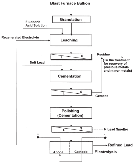
Figure 4 is a flowchart showing the unit
operations for the overall process from granulation of the bullion to refined
lead. The direct leaching of the bullion in fluoboric acid solution provides
a major departure from conventional lead refining because drossing is not required.
The results from the pilot plant evaluation show that granulating the bullion
as it exits the smelting furnace provides a novel option and the bullion could
then be refined by electrolytic deposition. Until a final polishing step, the
entire refining process can be conducted at temperatures in which lead fumes
are not created.
The robustness of this new lead refining process assures that a lead producer will have more flexibility in choice of smelter feed material, as bismuth and other impurity metals do not pose unique refinery problems common in conventional processes. Because the granulation-leaching-electrowinning process does not require drossing, emissions associated with bullion transfer and the increasing cost of managing such emissions can be eliminated. As the bullion is immediately leached, silver and gold contained in the leach residue are available for processing much sooner than presently practiced.
References
1. S. Wang, F,
Ojebuoboh, and M.G. King, “The Fluoborate Treatment of Sludge from the
Electrolytic Refining of Granulated Lead,” in this
issue.
2. T.R.A. Davey, “The
Physical Chemistry of Lead Refining,” Lead–Zinc–Tin ’80,
ed. J.M. Cigan et. al. (Warrendale, PA: TMS,
1980), pp. 477–507.
3. J.A. González-Domínguez,
E. Peters, and D.B. Dreisinger, “The Refining of Lead by the Betts Process,”
J.
Applied Electrochemistry, 21 (1991), pp. 189–202.
4. G.W. Toop, “Pyrometallurigical
Operations of the Cominco Lead-Zinc Smelter,” CIM
Bulletin (September 1994), pp. 89–92.
5. E. Nomura et al.,
“Recent Lead Electrolytic Refining Practice at Mitsui’s Kamioka
Lead Plant,” TMS Paper selection A81-1 (Warrendale, PA: TMS,
1981).
6. F.K. Ojebuoboh,
“One Ton of Bismuth in the Lead Smelter and 60 Years of Kroll-Betterton,”
CIM Bulletin,
89 (1003) (September 1996), pp. 76–79.
7. M. Olper and P.L.
Fracchia, “Hydrometallurgical Process for an Overall Recovery of the Components
of Exhausted Lead-Acid Batteries,” U.S. patent 4,769,116 (6 September
1988).
8. M. Olper and P.L.
Fracchia, “Process for Producing Electrolytic Lead and Elemental Sulfur
from Galena,” U.S. patent 5,039,337 (13 August 1991).
9. M. Olper and M.
Maccagni, “The Production of Electrolytic Lead and Elementary Sulphur
from Lead Sulfide Concentrates,” Hydrometallurgy, ed. J.B. Hiskey
and G.W. Warren (Warrendale, PA: TMS, 1993),
pp. 1,147–1,167.
For more information, contact F. Ojebuoboh, Asarco, 495 E. 51st Avenue, Denver, Colorado 80216; e-mail fojebuoboh@asarco.com.
Direct questions about this or any other JOM page to jom@tms.org.
| Search | TMS Document Center | Subscriptions | Other Hypertext Articles | JOM | TMS OnLine |
|---|