An Article from the March 2004 JOM: A Hypertext-Enhanced Article
|
TMS
ONLINE | TMS
PUBLICATIONS | SITE
MAP An Article from the March 2004 JOM: A Hypertext-Enhanced Article |
|
|
|
| Paul Cleary, Mahesh Prakash, Joseph Ha, and Matthew Sinnott are with Commonwealth Scientific and Research Organisation (CSIRO) Mathematical and Information Sciences in Clayton, VIC, Australia. Thang Nguyen and John Grandfield are with CSIRO Manufacturing and Infrastructure Technology in Preston, VIC, Australia. |
Exploring traditional, innovative, and revolutionary issues in the minerals,
metals, and materials fields.
|
| OUR LATEST ISSUE |
|
||
Overview: Process Modeling
Modeling of Cast Systems Using Smoothed-Particle Hydrodynamics |
To understand and control the filling process for metals in high-pressure die casting and ingot casting, researchers have used new flow-simulation software for the modeling of mold filling. Smoothed-particle hydrodynamics (SPH) is a non-conventional computational fluid dynamics method that has been successfully applied to these problems. Due to its mesh-free nature, it can handle complex splashing free surface flows and the differential motion of multiple solid-casting equipment components relatively easily. The ability of SPH to predict the detailed filling patterns of real large-scale automotive die castings is demonstrated in this study, and the use of SPH simulation for wheel shape optimization in ingot casting based on minimizing oxide generation while increasing the throughput is also presented.
High-pressure die casting is an important process in the manufacturing of high-volume and low-cost automotive components such as automatic transmission housings and gear box components. Liquid metal (generally aluminum or magnesium) is injected into the die at high speeds (30 m/s to 100 m/s) and under high pressure through complex gate and runner systems. The geometric complexity of the dies leads to strongly three-dimensional (3-D) fluid flow with significant free-surface fragmentation and splashing. The order in which the various parts of the die fill and the positioning of the air vents are crucial to forming homogeneous cast components with minimal entrapped voids. This is influenced by the design of the gating system and the geometry of the die. Numerical simulation offers a powerful and cost-effective way to study the effectiveness of different die designs and filling processes, ultimately leading to improvements in both product quality and process productivity, including more effective control of the die filling and die thermal performance.
The ingot chain conveyer casting process is commercially important to the aluminum industry, with millions of tonnes cast every year. In this process, cast iron molds on a conveyer are fed with molten metal, usually by a rotating wheel filling system. The ingot molds have a translational motion synchronized with the rotation of the wheel. The flow thus generated is complex and highly 3-D.
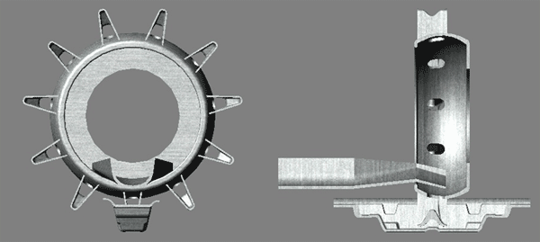
One of the important attributes of the ingots is the amount of dross/oxide present and the appearance of the ingot. This dross is produced during the filling of the mold. Increasing machine throughput means that the filling time is reduced and there may be greater turbulence and potentially increased dross generation. Most conventional fluid flow packages cannot handle the difficulty of moving the solid surfaces (wheel and mold) within the domain. Modeling of oxide generation is also a relatively new area where a Lagrangian method that tracks particles and their properties has an advantage. Typical ingot production rates in the industry are in the 18–20 t/h range. One of the main aims of the work described here was to develop an ingot wheel design that produces ingots at the rate of 30 t/h with minimal dross formation. Figure 1 is an example of a wheel design that is currently being used in the industry.
|
|
 |
|
Figure 1. The base case ingot wheel design used in the industry. |
|
Animation 1. The oxide distribution in fluid as it flows from the launder into the wheel and fills the ingots via the nozzles in the wheel. The original wheel design is shown in this video. Oxide is generated at exposed surfaces, with some mixed into the fluid and some remaining on the surface. |
|
|
Smoothed-particle hydrodynamics (SPH) is a Lagrangian method for modeling heat and mass flows. Due to its mesh-free nature and the handling of boundaries using SPH nodes, this method can handle complex splashing and fragmenting free surface flows and the motion of multiple solid equipment parts relatively easily. In traditional mesh-based methods used in commercial fluid-flow packages, large mesh deformations are generated by the motion of the equipment, leading to significant numerical problems. In addition, the tracking of the free surface is diffusive and inaccurate for the resolutions used.
For SPH, materials are discretized into particles that can move subject to equations of motion arising from the governing partial differential equations. The particles are moving interpolation points that carry with them (convect) physical properties and state information, such as the mass of the fluid that the particle represents, its temperature, momentum, enthalpy, density, and other properties. The inter-particle forces are calculated by smoothing the information from nearby particles in a way that ensures that the resultant particle motion is consistent with the motion of a corresponding real fluid, as determined by the governing equation (e.g., the Navier-Stokes equations).
Smoothed-particle hydrodynamics has been developed over the past two decades, initially for astrophysical applications1 and, more recently, for incompressible enclosed flows.2 It is also able to model low-speed incompressible flow,3,4 viscous flow,5 underwater explosions,6 and galaxy formation.7 Examples of other applications include heat conduction,8 natural convection in a cavity and Rayleigh-Benard convective instability,9 and geophysical flows.10 The isothermal equations used for the present simulations can be found in Reference 11.
This article aims to illustrate the ability of SPH to correctly predict the location of voids in complex cast components and to perform ingot casting simulations having 3-D geometries with complicated motions finally leading to design optimization on the basis of reduced oxide formation for high flow rates.
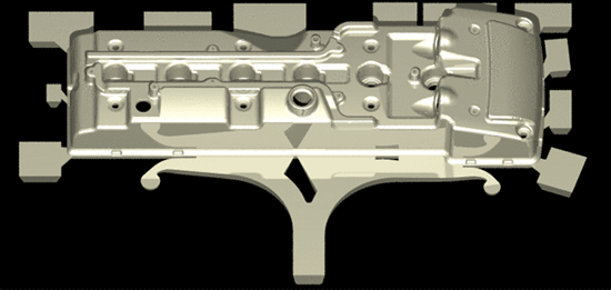
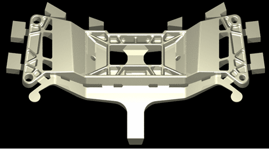
In SPH simulations of the filling of two complex automotive components, the results provide information on the order of fill and, therefore, indicate potential regions of porosity/voidage formation. Figure 2a shows the casting configuration for an engine rocker cover and Figure 2b shows a structural cross member.
|
|
|
 |
 |
| a | b |
|
Figure 2. A full casting shot geometry of (a) an engine rocker cover, and (b) a cross member. |
|
|
|
|
|
|
|
 |
 |
| a | b |
|
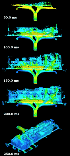
Figure 3. The filling of (a) an engine rocker cover and (b) a structural cross member. |
|
|
|
|
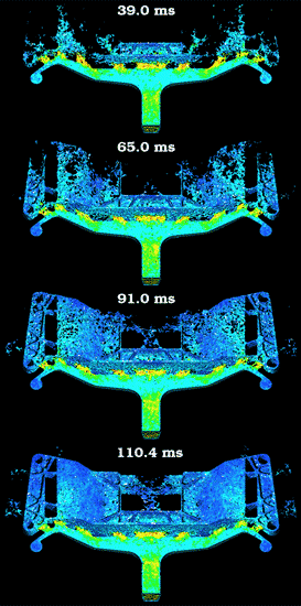
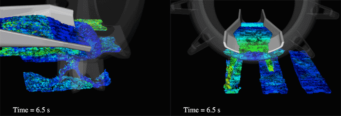
The rocker cover is about 750 mm × 250 mm in the projected area with a section thickness of about 3 mm. A tangential runner system directs metal through a gate with a width of 2 mm and gate speed of about 12 m/s. The SPH particle size used for this simulation was 1.25 mm. Figure 3a shows the filling of the rocker cover. The three long gates have an area that is similar to the runner cross-sectional area, so the fluid does not accelerate much in the gate region. There is less splashing and fragmentation of the fluid upon entry into the die than expected in normal high-pressure die-casting practice. In the early stages of the die filling, the fluid tends to fill the central section of the rocker cover first in spite of having long gates. Also, the complex stepped contours of the die lead to sustained void areas for long periods of the filling process. This is essentially the result of the inability of the diverging flow from the gate to maintain a uniform front, so fluid cannot flow into the more protected regions of the die produced by the steps in the shape. Note that there is also clear evidence of preferential race tracking of fluid around the perimeter of the rocker cover. By 250 ms, the die is substantially filled with critical voids remaining in two locations, one just to the side of the gate as seen in the fourth frame of Figure 3a and one on the far side of the casting where recirculating fluid has created a long-lived roughly elliptical void (last frame of Figure 3a). These are consistent with observations made by the manufacturer.
Figure 3b shows the filling of the cross bar support. This part is topologically complex, consisting of several sections with strengthening ribs and various cutouts. There are nine gates distributed along the leading edge of the component and these are fed by a fairly conventional tangential runner system with shock absorbers at the ends. The gate width is 2.6 mm and the particle resolution used for this simulation was 1.7 mm. This die is interesting because of the partitioning created by the large holes in the part and the high-aspect-ratio ribs. The fluid sprays out from the gate along clearly preferred pathways, leaving regions with long enduring voids on the sides of the central body where insufficient fluid can be supplied by this runner system. By 65 ms, the leading fluid fronts reach the far side of the die and much of the structure on the near side of the die is substantially filled. By 91 ms, the entire die is mostly filled, but many areas still exhibit distinct moderate scale voidage. The final area to fill is in the middle of the far side of the die. This is a structurally critical location where porosity is highly undesirable. The simulation shows that despite the presence of a large central bridge intended to channel fluid into this region much earlier, this region is difficult to fill and could be subject to trapped air and cold shut problems where the fronts of fluid meet from either side.
The base case used for the SPH simulations was an existing wheel design used in the aluminum casting industry (Figure 1). This design suffered from a number of cascades and unnecessary changes in fluid flow direction. A process of design evolution was used to optimize the design by assessing the results from the SPH simulation and modifying the design. In the process of evolving the design to a final optimal model, six new different wheel designs were developed and simulated using SPH. The final design minimizes flow direction changes and falling height. It gently guides the flow into the mold along the long axis of the molds so that little of the liquid jet is directed against the mold walls.
An important consideration in arriving at an optimal wheel design was the need to increase throughput while keeping the oxide content low. Oxide grows on the surface of the molten aluminum. The growth rate depends on the melt temperature and the alloy composition. This oxide layer can be broken by the flow of the aluminum, creating a new surface. Any splashing will result in droplets of melt surrounded by oxide film, which become dross on the melt surface. Most of the studies presented in the literature report oxidation kinetics over long periods of time usually ranging from minutes to hours in stagnant melts.12–14 Few studies have examined oxide/dross generation during melt transfer (which is a rapid process), yet it is well known that considerable dross is generated during pouring from one height to another or during flow under or over obstacles. Experiments by Baker et al.15 indicate that the amount of dross is proportional to the falling height. Their work was used to predict the amount of oxide formed in the simulations. The linear oxide growth model has the form:
(1) |
for the oxide where Woxide is the oxide content, Sarea is the exposed surface area, kl is the rate constant, and t is time. Baker et al. empirically calculated the rate constant to be 10.9 × 10⁻³ kg/m2 s.
A bank of four ingot molds was used for all seven wheel designs, with ingots produced at the rate of 30 t/h. The synchronized linear ingot mold bank speed was 6 m/min. The rotational speed of the ingot wheel was adjusted accordingly. The base case wheel design (Figure 1) was also simulated with an ingot casting rate of 20 t/h (or synchronized linear ingot mold bank speed of 4 m/min.) for comparison. Each simulation was run until all four molds were filled. The time delay in fluid flow through the launder and wheel meant that the first mold was only partially filled in all cases.
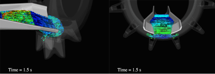
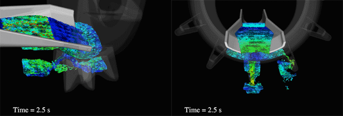
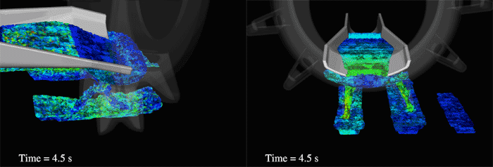
Model results show surface oxide levels and velocity and flow patterns (Figures 4a, 4b, 4c, and 4d) for the original design (Figure 1). The corresponding videos with oxide distribution and velocity are given in Animations 1 and 2 respectively. The wheel in Figures 4a, 4b, 4c, and 4d is made semitransparent in order to clearly show the flow pattern and oxide levels. An oblique side view is chosen to show the oxide data whereas a front view along the launder in the direction of the flow shows the velocity distribution. In Figures 4a, 4b, 4c, and 4d, the oxide content is colored from blue (minimum) to red (maximum) depending on the amount of oxide present. An oxide reset plane is used at the tip of the launder just before the flow starts going into the wheel in order to set the oxide values to zero and determine oxide generation due only to the flow into the wheel and through to the ingot molds.
|
|
 |
| a |
 |
| b |
 |
| c |
 |
| d |
|
Figure 4. The predicted oxide distribution and velocities for original wheel design at different times. Note that the oxide distribution is shown with an oblique side view and the velocity distribution is shown with a front view along the launder and in the direction of the flow. The molds are moving from left to right. |
|
Animation 2. The flow velocity as fluid flows from the launder into the wheel. The velocity is colored from red (maximum) to blue (minimum). This view shows the fluid (with a predominantly blue color) creating a shallow pool in the wheel before flowing into the ingot through the nozzles. The original wheel design is shown in this video. |
| |
|
|
The fluid flows through the launder, into the wheel, and finally into the mold through the nozzles. In the original design (Figure 1), at the end of the launder its profile becomes steeper. This causes the fluid to accelerate under gravity before entering the wheel (Figure 4a). The fluid then strikes the back of the wheel and the flow is reflected, forming a pool in the base of the wheel (Figure 4b). This fluid feeds into each nozzle through outlet ports in the base of the wheel (Figure 1). Due to this constriction, the weight of accumulated fluid in the wheel generates a high-velocity flow into the top of the nozzle (Figure 4c). The use of two nozzle outlets splits the flow, creating higher surface area to volume. Material entering the ingot mold reflects off the front and back walls of each mold (Figures 4b and 4c). These two waves meet in the center of the mold again, causing increased splashing and significant surface fragmentation. All these effects tended to increase surface area and oxidation in the old design.
|
|
 |
|
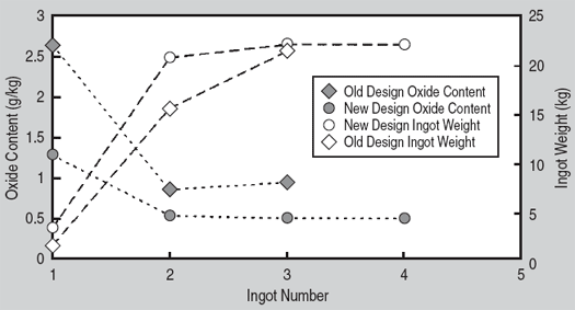
Figure 5. The predicted ingot oxide content and weights for the old and new wheel designs at 30 t/h. |
|
|
Figure 4d shows the system when filling of the third ingot is almost complete. From the frames showing the velocity distribution in Figures 4a, 4b, 4c, and 4d, one can see that the wheel rotates in the anticlockwise direction and the ingot molds move to the right. In the later stages of the filling process, the flow becomes established with the flow into the mold, following a somewhat repetitive pattern. The model predicts that it takes three to four ingots before the pool of fluid in the wheel has sufficiently built up for the system to stabilize in terms of ingot weight and oxide content (Figure 5).
The oxide level predictions for the 20 t/h (0.92 g/kg) and 30 t/h (0.95 g/kg) original design are quite comparable. This suggests that at both production rates, the flow characteristics in terms of the amount of new surface exposed should be similar. In other words, the oxide content seems to be independent of the Reynolds number for this range of fluid velocity. Predictions indicate that the optimized design should produce ingots with much lower oxide levels (0.51 g/kg) than the established design. In most cases, the oxide was split equally between the surface and the interior of the ingot.
This project was funded by the Cooperative Research Centre (CRC) for Cast Metals Manufacturing (CAST), which was established under and is supported in part by the Australian government’s CRC scheme. The Commonwealth Scientific and Industrial Research Organisation and ODT Engineering Pty. Ltd., Melbourne, Australia are core members of CAST.
1. J.J. Monaghan, “Smoothed Particle Hydrodynamics,” Ann. Rev. Astron. Astrophys., 30 (1992), pp. 543–574.
2. J.J. Monaghan, “Simulating Free Surface Flows with
SPH,” J. Comp. Phys., 110 (1994), pp. 399–406.
3. J.P. Morris, P.J. Fox, and Y. Zhu, “Modelling Low
Reynolds Number Incompressible Flows using SPH,” J.
Comp. Phys., 136 (1997), pp. 214–226.
4. S.J. Cummins and M. Rudman, “An SPH Projection
Method,” J. Comp. Phys., 152 (1999), pp. 584–607.
5. H. Takeda, S.M. Miyama, and M. Sekiya, “Numerical
Simulation of Viscous Flow by Smoothed Particle
Hydrodynamics,” Prog. Theoretical Physics, 92 (1994),
pp. 939–960.
6. J.W. Swegle and S.W. Attaway, “On the Feasibility of
Using Smoothed Particle Hydrodynamic for Underwater
Explosion Calculations,” Comput. Mechanics, 17
(1995), p. 151.
7. J. Hultman and D. Kallander, “An SPH Code for
Galaxy Formation Problems: Presentation of the Code,” Astron. Astrophys., 324 (1997), pp. 534–548.
8. P.W. Cleary and J.J. Monaghan, “Conduction
Modelling Using Smoothed Particle Hydrodynamics,” J.
Comp. Phys., 148 (1999), pp. 227–264.
9. P.W. Cleary, “Modelling Confined Multi-Material Heat
and Mass Flows Using SPH,” Applied Math. Modelling, 22 (1998), pp. 981–993.
10. M. Prakash, F. Debroux, and P.W. Cleary, “Three
Dimensional Modelling of Dam-break Induced Flows
Using Smoothed Particle Hydrodynamics,” Proc. of
the 14th Australasian Fluid Mech. Conf. (Adelaide,
Australia: Causal Productions Pty Ltd., 2001), pp.
379–382.
11. P.W. Cleary et al., “Flow Modelling in Casting
Processes,” Applied Math. Modelling, 26 (2002),
pp. 171–190.
12. C.N. Cochran, D.L. Belitskus, and D.L. Kinosz, “
Oxidation of Aluminium-Melts in Air, Oxygen, Flue
Gas and Carbon Dioxide,” Metallurgical Transactions
B, 8B (1977), pp. 323–332.
13. D.J. Field, G.M. Scamans, and E.P. Butler, “The
High Temperature Oxidation of Al-4.2 Wt Pct Mg
Alloy,” Metallurgical Transactions A, 18A (1987), pp.
463–472.
14. E. Bergsmark, C.J. Simensen, and P. Kofstad, “The
Oxidation of Molten Aluminium,” Material Science and
Engineering, A120 (1989), pp. 91–95.
15. P.W. Baker, K. Nguyen, and R. Kirkaldie, Aluminium
Cast House Technology 4th Australasian Asian Pacific
Conference, ed. M. Nilmani (Warrendale, PA: TMS,
1995), p. 109.
For more information, contact John F. Grandfield, CSIRO Manufacturing Science and Technology, Albert and Raglan Streets, Preston, VIC 3072, Australia; +61-3-9662-7832; fax +61-3-9662-7770; e-mail john.grandfield@csiro.au.
Direct questions about this or any other JOM page to jom@tms.org.
| Search | TMS Document Center | Subscriptions | Other Hypertext Articles | JOM | TMS OnLine |
|---|