An Article from the December 2003 JOM-e: A Web-Only Supplement to JOM
|
TMS
ONLINE | TMS
PUBLICATIONS | SITE
MAP An Article from the December 2003 JOM-e: A Web-Only Supplement to JOM |
|
|
|
|
Y. Austin Chang is Wisconsin Distinguished Professor in the Department of Materials Science and Engineering at the University of Wisconsin and W.A. Oates is Honorary Professor at the Science Research Institute, University of Salford, England.
|
Exploring traditional, innovative, and revolutionary issues in the minerals,
metals, and materials fields.
|
| OUR LATEST ISSUE |
|
|
OTHER ARTICLES IN THE SERIES |
|---|
|
|
|
Since the early 1990s, one of the authors, Y.A. Chang, has been teaching a thermodynamics course at the University of Wisconsin at Madison (UW-Madison), primarily for first-year graduate students, and also a senior-level phase-diagrams course. When Chang became president of TMS in 2000, Oates, a visiting professor at UW-Madison for the fall semester, taught the thermodynamics course. The two of us have since jointly been teaching this class. In this article, we select two topics from this course that illustrate, first, our use of computational thermodynamics in the thermodynamics class. This class helps the students comprehend the inter-relationships between the relative thermodynamic stabilities of the phases involved and the characteristic features of the binary phase diagrams. The selected topics illustrate, second, the use of multicomponent phase diagrams in the phase-diagram class, calculated thermodynamically or obtained experimentally, for materials design, specifically for designing contacts to GaAs. Due to the time limitations, Chang presented only the first part at the symposium on Computational Methods in Materials Education held at the 2003 TMS Annual Meeting in San Diego, California. Here, we present both examples.
Phase diagrams and thermodynamics, which are closely related, can be viewed as the same subject. When the thermodynamic properties of all the phases in a system are known the phase diagram can be calculated. Years ago, due to the difficulty in hand-calculating even the simplest of phase diagrams from thermodynamic properties, these two subjects were usually treated as separate disciplines in materials science and engineering courses. The arrival of fast and cheap computers and robust software has changed the situation both in terms of the actual computation and in the graphical presentation of the results. As a result, students can now readily appreciate the topological features of a phase diagram in terms of the relative stabilities of the phases involved. After introducing the principles of solution thermodynamics, including a discussion of the basic solution models for disordered alloys, we then introduce the mathematical formulations in terms of the Gibbs energies of phases as functions of composition and temperature in order to calculate simple binary phase diagrams.
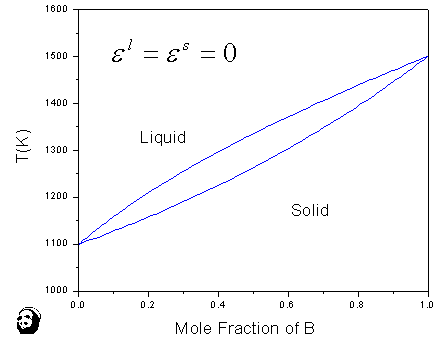
In this article, we will present neither the definitions of all the thermodynamic quantities nor the derivations of the relevant equations for calculating phase diagrams. For those details, the reader can refer to one of the many textbooks on the thermodynamics of materials such as Darken and Gurry1, DeHoff2, Devereux3, Gaskell4 and Swalin.5 Figure 1a shows a phase diagram for a hypothetical binary system, A-B, where solid A and solid B exhibit the same crystal structure (e.g., face-centered cubic [fcc]). In Chapter 9 of his textbook, Swalin5 presents such a figure with the caption indicating that it is a phase diagram for an ideal solution. In this paper, we will refer to the shape of such liquidus/solidus curves as cigar-shaped. It is true that the phase diagram shown in Figure 1a can be calculated assuming ideal solution behavior for both the solid and liquid phases (i.e., where the regular solution parameters for the liquid and solid phases, el and eS, are both zero). The melting temperatures and entropies of fusion (or melting) used in the calculation of Figure 1a are ![]() (A) = 1,100 K, DfusS0 (A) = 20 J mol-1 K-1 and
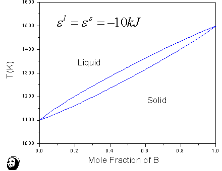
(A) = 1,100 K, DfusS0 (A) = 20 J mol-1 K-1 and ![]() (B) = 1,500 K, DfusS0 (B) = 20 J mol-1 K-1. However, the converse is not true (i.e., we may have a cigar-shaped diagram even when the behavior of the solutions is non-ideal). Moreover, a non-cigar-shaped phase diagram does not necessarily mean that the solutions are not ideal. The shapes of the liquidus/solidus curves depend on the melting points of A and B, the entropies of melting for A and B, and the solution behavior of the liquid and solid phases. As shown in Figure 1b, the shape of the liquidus/solidus is indeed cigar-shaped, similar to that shown in Figure 1a, yet, the liquid and solid phases do not behave ideally. The melting temperatures and entropies of melting are the same as those used in calculating Figure 1a but the liquid and solid in this case deviate negatively from ideal behavior (i.e., el = e6 = -10 kJ mol-1). The phase diagrams shown in Figure 1a and subsequent figures were calculated using the PANDAT computer software packadge.6 A description in the use of this software is given in Appendix I and in this month’s issue of JOM.
(B) = 1,500 K, DfusS0 (B) = 20 J mol-1 K-1. However, the converse is not true (i.e., we may have a cigar-shaped diagram even when the behavior of the solutions is non-ideal). Moreover, a non-cigar-shaped phase diagram does not necessarily mean that the solutions are not ideal. The shapes of the liquidus/solidus curves depend on the melting points of A and B, the entropies of melting for A and B, and the solution behavior of the liquid and solid phases. As shown in Figure 1b, the shape of the liquidus/solidus is indeed cigar-shaped, similar to that shown in Figure 1a, yet, the liquid and solid phases do not behave ideally. The melting temperatures and entropies of melting are the same as those used in calculating Figure 1a but the liquid and solid in this case deviate negatively from ideal behavior (i.e., el = e6 = -10 kJ mol-1). The phase diagrams shown in Figure 1a and subsequent figures were calculated using the PANDAT computer software packadge.6 A description in the use of this software is given in Appendix I and in this month’s issue of JOM.
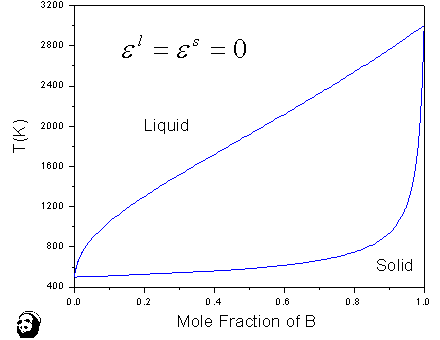
On the contrary, the shape of liquidus/solidus curves given in Figure 1c look quite different from those in Figure 1a and yet that diagram was calculated assuming ideal behavior for both the liquid and solid phases (i.e., el = e6 = 0). The thermodynamic properties of pure A and B used differ, however, from those used in calculating Figure 1a: ![]() (A) = 400 K, DfusS0 (A) = 40 J mol-1 K-1;
(A) = 400 K, DfusS0 (A) = 40 J mol-1 K-1; ![]() (B) = 3,000 K, DfusS0 (B)= 10 J mol-1 K-1 . It is clear that the melting temperatures and entropies of melting of A and B have a profound effect on the shape of the liquidus/solidus curves in this case.
(B) = 3,000 K, DfusS0 (B)= 10 J mol-1 K-1 . It is clear that the melting temperatures and entropies of melting of A and B have a profound effect on the shape of the liquidus/solidus curves in this case.
In the following examples, calculated binary phase diagrams for the hypothetical A-B system show quite different topological features arising only from the choice of the solution behaviors of the solid and liquid phases (i.e., we use the same melting temperatures and entropies of melting of A and B but change the regular solution parameters of the solid and liquid phases). Using the elemental data ![]() (A) = 800 K, DfusS0 (A) = 20 J mol-1 K-1;
(A) = 800 K, DfusS0 (A) = 20 J mol-1 K-1; ![]() (B) = 1,000 K, DfusS0 (B) = 20 J mol-1 K-1, we walk through the steps in calculating these phase diagrams using the PANDAT6 software.
(B) = 1,000 K, DfusS0 (B) = 20 J mol-1 K-1, we walk through the steps in calculating these phase diagrams using the PANDAT6 software.
|
|
||
 |
 |
 |
| a | b | c |
|
Figure 1. (a) The phase diagram of A-B, calculated using |
||
|
|
||
Cigar-Shaped Phase Diagram
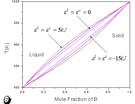
Figure 2 shows three cigar-shaped phase diagrams. When the values of the regular solution parameters of both phases are equal and positive (i.e., positive deviations from ideal behavior), the width of the melting region and the values of the parameters become larger. On the other hand, when the values of the regular solution parameters are equal and negative (i.e., negative deviation from ideal behavior), the width of the melting region becomes narrower. It is worth noting that Wagner7 showed that the calculated width of the liquidus/solidus region for Ag-Au at 50 mol% was 1.3°C assuming ideal behavior for the liquid and solid phases. Yet the experimental measured value was close to 10°C. Knowing that these alloys deviate negatively from ideal behavior, Wagner concluded that the width of the melting region must be smaller than 1.3°C, indicating that the experimentally determined value of 10°C must be in error. These calculations indicate a cigar-shaped diagram is obtained when the relative stabilities of the liquid and solid phases are comparable and when the melting points and entropies of fusion for the two component elements, A and B, remain the same.
|
|
||
 |
 |
|
|
Figure 2. The cigar-shaped phase diagram of A-B calculated using |
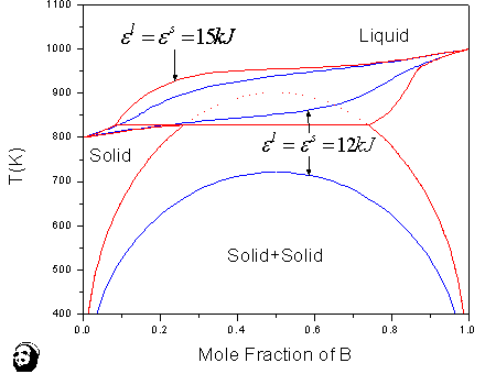
Figure 3. The cigar-shaped phase diagram of A-B with a solid miscibility gap (blue color) calculated using el = e6 = 12 kJ mol-1, and peritectic phase diagram of A-B calculated using el = e6 = 15 kJ mol-1. The thermodynamic data for A and B are the same as those given in Figure 2. |
|
|
|
Peritectic Phase Diagrams
Peritectic phase diagrams can occur when the relative stabilities of both phases are comparable, the regular solution parameters for both phases are positive, and the critical temperature, Tc, for the (metastable) miscibility gap of the solid phase intercepts the (metastable) solidus curve. Figure 3 shows two phase diagrams for our A-B system; one is cigar-shaped with a solid miscibility gap shown in blue and the other, shown in red, is for peritectic formation. In the first case, the regular solution parameter for the solid phase is 12 J mol-1 with a value of Tc = 721.7 K. When the Tc = 902.1 K (meaning a higher e6 = 15 kJ mol-1), the metastable miscibility gap intercepts the metastable solidus curve and a peritectic equilibrium results. Since the metastable solidus curve calculated using e6 = 15 kJ mol-1 would not differ appreciably from that calculated using e6 = 12 kJ mol-1, it is not shown in this figure for clarity.
Phase Diagrams with Maximum and Minimum Congruent Melting Points
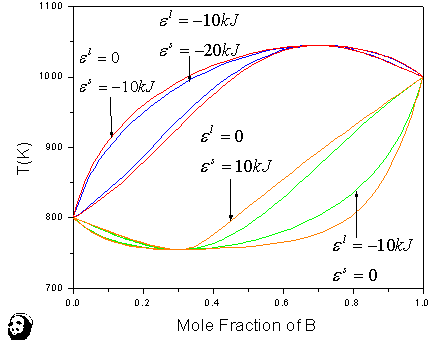
The congruent melting of solid solutions occurs when the temperature is either a maximum or a minimum as dictated by thermodynamics. A maximum occurs when the solid phase is more stable than the liquid phase and vice versa. Figure 4 shows calculated phase diagrams using two groups of thermodynamic parameters. One group consists of el = 0, e6 = -10 kJ mol-1 and el = -10 kJ mol-1, e6 = -20 kJ mol-1 and the other consists of el = - 10 kJ mol-1, e6 = 0, and el = 0, e6 = 10 kJ mol-1. As shown in this figure, the phase diagrams calculated using the two sets of solution parameters in the first group are essentially the same. We use this example in class to emphasize the important thermodynamic point that the topology of phase equilibria is governed by the relative stabilities of the phases involved. In the first group, the liquid is ideal in one case (i.e., el = 0) and exothermic in the other (i.e., el = - 10 kJ mol-1). Yet the calculated phase diagram is essentially the same in both cases. These results are exactly what one expects since the regular solution parameter values of the solid phase in both cases are 10 kJ mol-1 more exothermic than those of the liquid phase. In other words, the solid is thermodynamically more stable than the liquid phase. Intuitively these results make sense. The more stable the solid phase relative to the liquid phase higher the melting. The calculated phase diagrams for the two sets of parameters given in the second group are also shown in Figure 4. The calculated liquidus/solidus curves are essentially the same as those in the first group since these curves are governed by the relative stabilities of these two phases. However, there is one difference: a miscibility gap occurs in the solid phase. This is due to the fact that the single-phase solid solution becomes less stable when compared with a mixture of two solid phases with different compositions.
|
|
||
 |
 |
|
|
Figure 4. The phase diagrams of A-B with maximum and minimum congruent melting points calculated using el = 0 and e6 = -10 kJ mol-1, el = -10 and e6 = -20 kJ mol-1, el = -10 kJ mol-1 and e6 = 0, and el = 0 and e6 = 10 kJ mol-1. The thermodynamic data for A and B are the same as those given in Figure 2. |
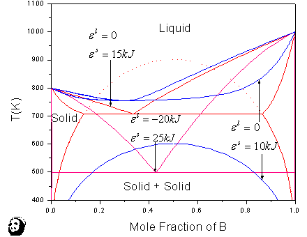
Figure 5. The eutectic phase diagrams of A-B calculated using three sets of solution parameters: el = 0 and e6 = 10 kJ mol-1, el = 0 and e6 = 15 kJ mol-1, and el = -20 kJ mol-1and e6 = 25 kJ mol-1. The thermodynamic data for A and B are the same as those given in Figure 2. |
|
|
|
Eutectic Phase Diagrams
As shown in Figure 5, the calculated phase diagram (in blue) using the first set of parameters, el = 0, e6 = 10 kJ mol-1, are topologically similar to one of the phase diagrams presented in Figure 4. There is a minimum congruent melting point and a miscibility gap in the solid phase. However, in the second case the solid is less stable with a value of e6 = 15 kJ mol-1 and el = 0 as in the first case, the metastable solid miscibility gap intersects the liquidus of the metastable liquid/solid equilibrium. A eutectic equilibrium forms (in orange). Following the previous discussion, it becomes obvious that the liquid phase exists to lower temperatures because it becomes thermodynamically more stable than the solid phase. When we change el from 0 kJ mol-1 to -20 kJ mol-1 and e6 from 15 kJ mol-1 to 25 kJ mol-1, the liquid phase becomes stable to an even lower temperature. We may refer to this phase diagram as one exhibiting a deep eutectic. It is in alloys where deep eutectics are formed that tend to form glasses whether in metallic or non-metallic systems. Note, however, that thermodynamics alone do not dictate the formation of a glass phase; kinetics also play a role. As shown in Figure 5, alloys with compositions in the vicinity of the eutectic are stable at temperatures that are relatively low when compared with those of the melting points of A and B. Since lower temperatures favor increasing viscosity and decreasing diffusivity, under such conditions, when such an alloy is solidified, there may not be enough time for the nucleation of crystalline solids and a glass may therefore form.
Monotectic, Syntectic, and Monotectic + Syntectic Phase Diagrams
It is noteworthy to point out that Van Laar8,9 laboriously calculated these types of phase diagrams by hand nearly a century ago using the regular solution model, whereas students can now use computer software like PANDAT6 or WinPhad10 to vary the solution parameters of the liquid and solid phases and calculate a large number of such diagrams with different topological features in a matter of seconds (See Appendix I for a step-by-step procedure for performing those calculations). Although we do not extend what we teach about binaries to multicomponent systems in the first-year graduate thermodynamics class, this type of calculation is readily extended to ternaries using PANDAT. Meijering11–13 performed such calculations by hand half a century ago.
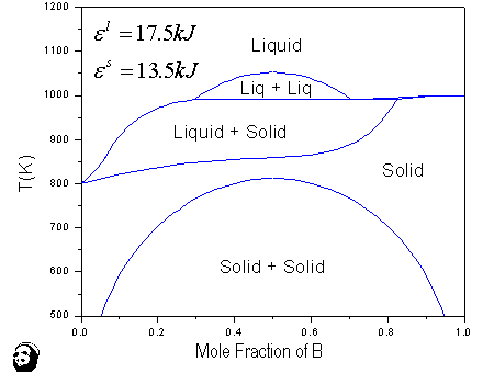
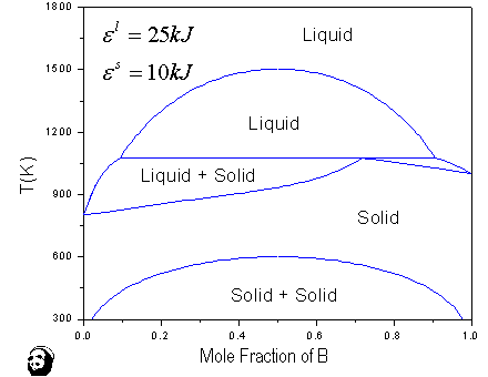
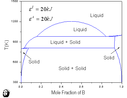
These types of phase diagrams occur when the formation of both the liquid and solid phases is endothermic. Figures 6a, 6b, and 6c show three such phase diagrams calculated using the following thermodynamic parameters (a) el = 17.5 kJ mol-1, e6 = 13.5 kJ mol-1, (b) el = 25 kJ mol-1, e6 = 10 kJ mol-1, and (c) el = 20 kJ mol-1, e6 = 20 kJ mol-1.
|
|
||
 |
 |
 |
| a | b | c |
|
Figure 6. (a) The monotectic phase diagram of A-B calculated using el = 17.5 kJ mol-1 and eS = 13.5 kJ mol-1. The thermodynamic data for A and B are the same as those given in Figure 2. (b) The syntectic phase diagram of A-B calculated using el = 25 kJ mol-1 and eS = 10 kJ mol-1. The thermodynamic data for A and B are the same as those given in Figure 2. (c) The monotectic + peritectic phase diagram of A-B calculated using el = e6 = 20 kJ mol-1. The thermodynamic data for A and B are the same as those given in Figure 2. |
||
|
|
||
Constrained Phase Diagram
|
|
 |
|
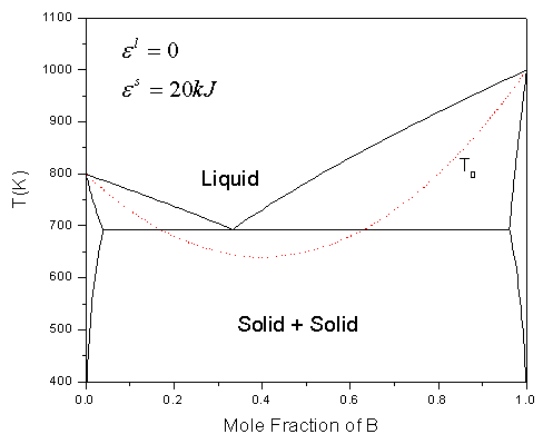
Figure 7. A eutectic phase diagram of A-B superimposed with the To curves for partitionless solidification/melting of the solid solutions. |
|
|
Figure 7 introduces the T0 curve in a simple eutectic phase diagram A-B. This curve is defined as the locus of the temperatures at which the Gibbs energies of the high- and low-temperature phases are equal. The curve shown in Figure 7 is for the metastable partitionless melting and freezing of alloys (A,B) and should have been labeled more precisely as ![]() . According to Figure 7, when a liquid is undercooled below the liquidus, when it intercepts the T0 curve, partitionless solidification may occur since the Gibbs energies of the both phases are equal. In reality, further undercooling is needed in order to promote nucleation of the solid from the liquid. Indeed, Duwez et al.14 showed it is possible to form a series of continuous solid solutions of fcc (Ag,Cu) and their lattice parameters follow Vegard’s law. There are other T0 curves, such as from a solid phase to another one with a different crystal structure. One familiar example is that for martensitic formation.
. According to Figure 7, when a liquid is undercooled below the liquidus, when it intercepts the T0 curve, partitionless solidification may occur since the Gibbs energies of the both phases are equal. In reality, further undercooling is needed in order to promote nucleation of the solid from the liquid. Indeed, Duwez et al.14 showed it is possible to form a series of continuous solid solutions of fcc (Ag,Cu) and their lattice parameters follow Vegard’s law. There are other T0 curves, such as from a solid phase to another one with a different crystal structure. One familiar example is that for martensitic formation.
Subsequent to introducing the basic principles of solution thermodynamics and phase diagrams in the undergraduate course, we give a number of examples in utilizing phase diagrams, particularly multicomponent ones, for engineering applications. Here we select a specific example of the use of phase diagrams in rationalizing and ultimately designing ohmic and Schottky contacts to n-GaAs and other compound semiconductors.
There was a considerable amount of effort in the late 1980s/early 1990s toward the development of new materials to replace the standard Au-Ni-Ge materials as ohmic contacts to n-GaAs. Au-Ni-Ge materials are considered as alloyed contacts because contact formation depends on the presence of liquid phases. The existence of low-melting initial phases and reactions, leading to the formation of spikes in the substrate, makes them inherently unstable even at moderate temperatures such as 400°C which are required for device processing.15
Additionally, the ever-increasing miniaturization of devices makes these contacts even less desirable. One approach is to adapt alternative materials that undergo a solid-state reaction with the semiconductor substrate to form shallow contacts. One particularly interesting material developed at IBM at that time was based on a combination of nickel and indium.16–19 Indium was introduced with the hope that it would induce a solid-state reaction at the metal/semiconductor interface, forming an InAs-rich (Ga,In)As alloy. Since the InAs-rich semiconductor is a narrow band gap semiconductor, ohmic behavior should prevail. Ohmic behavior was indeed achieved with layers of Ni/In/Ni deposited on a substrate of n-GaAs but only when subjected to rapid thermal annealing (RTA) to ≈810°C for a few seconds. This phenomenon is more consistent with the formation of a liquid phase instead of a solid-state phase reaction. Since phase diagram information was not available, it was impossible to answer this fundamental question. We thus initiated a research program in the late 1980s to determine the high-temperature phase diagrams of Ga-As-Ni.20–24 As given in the following, the existence of ternary eutectic in this ternary system is responsible for the ohmic behavior.
|
|
||
 |
 |
 |
| a | b | c |
|
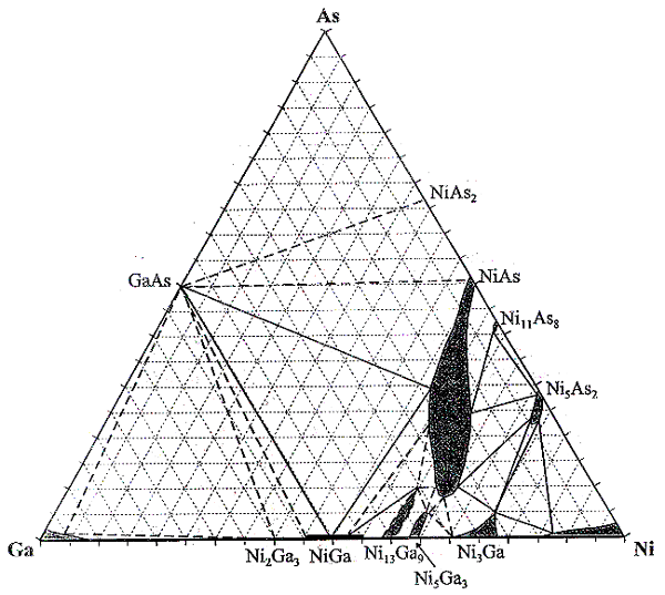
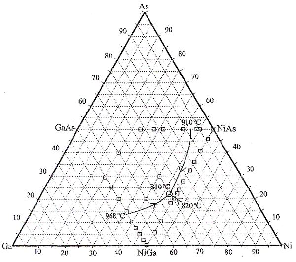
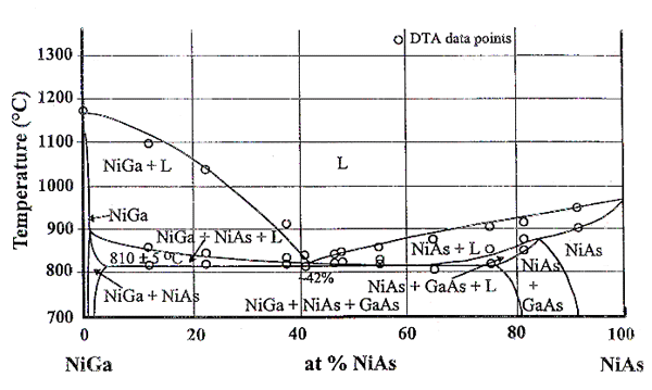
Figure 8. (a) A 600°C isotherm of Ga-As-Ni. (b) A partial liquidus projection of Ga-As-Ni. (c) An isopleth at 50 at.% Ni. |
||
|
|
||
Figures 8a and 8b show a 600°C isotherm and a liquidus projection of Ga-As-Ni respectively, and Figure 8c shows one isopleth at 50 mol % Ni.20–24 It is evident from Figure 8a that nickel is not in equilibrium with GaAs. Secondly, the (NiAs) phase, exhibiting a wide range of homogeneity, exists along the GaAs-Ni join. For simplicity, we will designate this phase with compositions along this join simply as Ni3GaAs even though it does exist over a range of nickel compositions. Diffusion couple measurements of GaAs/Ni showed the rapid formation of Ni3GaAs21,23 (initially instead of the stable phases). As a matter of fact, the high degree of metastability of the Ni3GaAs phase in this diffusion couple allows us to determine its diffusivities even at rather high temperatures, from 400°C to 700°C. Although this phase forms immediately when a nickel thin film is placed in contact with GaAs at a high temperature, it decomposes readily when all the nickel is consumed. This occurs because the overall composition moves toward GaAs and the resulting phases are GaAs, (NiAs), and NiGa. The composition of (NiAs) in this three-phase field is no longer Ni3GaAs but richer in NiAs, as shown in Figure 8a. Let us next examine the liquidus projection of Ga-As-Ni in Figure 8b and the isopleth between NiGa and NiAs in Figure 8c. As shown in Figure 8b, there exists a ternary eutectic, L = GaAs + NiGa + NiAs, at 810°C with the eutectic composition richer in GaAs along the GaAs-Ni join and richer in NiGa along the NiGa-NiAs join. The NiGa-NiAs isopleth given in Figure 8c shows the lowest melting temperature of the Ni(Ga1-xAsx) alloy is 820°C at about x = 0.42.
|
|
||
 |
 |
|
|
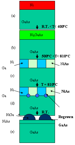
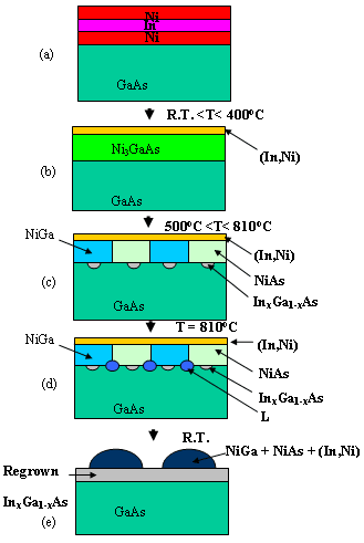
Figure 9. The phase formation sequence in nickel thin-film/GaAs contact: (a) as-deposited, (b) ambient < T < 400°C, (c) 500°C < T < 810°C, (d) T = 810°C, and (e) upon cooling to T below 810°C. |
Figure 10. The phase formation sequence in Ni/In/Ni thin-film/GaAs contact: (a) as-deposited, (b) ambient < T < 400°C, (c) 500°C < T < 810°C, (d) T = 810°C, and (e) upon cooling to below 810°C. |
|
|
|
On the basis of the ternary Ga-As-Ni phase equilibria and the rapid formation of Ni3GaAs at the Ni/GaAs interfaces, we can postulate a likely reaction sequence when a thin-film Ni (≈40 nm) /GaAs contact is subjected to RTA. Figure 9 shows, schematically, a postulated sequence of phase formation in such a contact. Once we understand the phase formation in this system, we can postulate a reaction sequence for a thin-film Ni/In/Ni/GaAs contact when subjected to a RTA treatment.
Figure 9a shows the as-deposited Ni/GaAs contact. Between ambient and T ≈ 400°C, Ni3GaAs forms consuming the entire thin-film nickel (Figure 9b). With either increasing time at 400°C or an increasing temperature, such as 500°C, or both, Ni3GaAs would react with GaAs moving to the three-phase region, GaAs + NiGa + (GaAs) (Figure 9c) (see discussion in the previous paragraph). When the temperature is further increased to 810°C, a liquid phase will form at the interfaces of GaAs, NiGa, and (NiAs) due to the ternary eutectic invariant reaction shown in Figure 9d. When the temperature is decreased to ambient, the liquid alloy will solidify most probably to form a layer of regrown GaAs on the substrate (Figure 9e).
Figure 10 shows a similar phase formation sequence of a Ni/In/Ni/GaAs contact. The as-deposited contact is given in Figure 10a. In order to predict what would happen next when compared with the Ni/GaAs contact, we must know something about the relative reaction rates at the interfaces of Ni/In and Ni/GaAs. The high diffusivity of nickel in the Ni3GaAs phase21 suggests that the rate of reaction at the GaAs/Ni interfaces to form Ni3GaAs will dominate when compared to that at the Ni/In interfaces. Furthermore, since indium melts at 153°C, it is likely that the Ni3GaAs phase would form with the simultaneous displacement of indium toward the top of the contact, with perhaps a minute amount of nickel in the indium liquid, as shown in Figure 10b. The Ni3GaAs phase would subsequently decompose into NiGa and NiAs with perhaps some limited reaction locally between indium and GaAs to form InxGa1-xAs as shown in Figure 10c. When the temperature of the contact is increased to 810°C, the eutectic liquid would form and the indium already liquid would mix with the molten eutectic layer. Upon solidification, when cooling to lower temperatures, a thin-layer of InxGa1-xAs would likely form epitaxially on the substrate of GaAs. Formation of this InAs-rich InxGa1-xAs layer will make the contact ohmic as has been found by Murakami et al.15–19 Jan, Swenson, and Chang25–27 had carried out experiments to verify the proposed reaction sequences shown in Figures 9 and 10. A more complete citation of the relevant literature on the Ni-In contact to n-GaAs can be found elsewhere.26–27
This example shows how phase diagram information allows us to rationalize the mechanism of the Ni/In ohmic contact formation to n-GaAs. On the other hand, if the phase diagram information were available then, one would have realized that the mechanism for ohmic contact formation was likely due to the existence of this ternary eutectic.
The authors wish to thank Fan-you Xie, Fan Zhang, and Shuanglin Chen of CompuTherm, LLC, for their help and suggestions in preparing this manuscript and for their critical comments towards its improvement. One of the authors, YAC, wishes to acknowledge the financial support of the National Science Foundation, International Copper Research Association, the Defense Advanced Research Projects Agency, NASA, U.S. Air Force, the U.S. Department of Energy, ALCOA, and Wisconsin Distinguished Professorship over the years for materials research conducted at the University of Wisconsin in alloy thermodynamics, phase diagrams, and kinetics. Although this support has been primarily for research, YAC has greatly benefited from pursuing research in this field and, hopefully, this has resulted in the improvement of his teaching the subject of thermodynamics/phase diagrams to the students.
1. L.S. Darken and R.W. Gurry, Physical Chemistry of Metals, (New York: McGraw-Hill, 1953).
2. R.T. deHoff, Thermodynamics in Materials Science, (New York:McGraw-Hill, 1993).
3. O.F. Devereux, Topics in Metallurgical Thermodynamics, (Hoboken, New Jersey: Wiley, 1983).
4. D. Gaskell, Introduction to Thermodynamics of Materials, 3rd ed. (London: Taylor & Francis, 1995).
5. R.A. Swalin, Thermodynamics of Solids, 2nd ed., (Hoboken, New Jersey: Wiley, 1972).
6. PANDAT™ Software for Multicomponent Phase Diagram Calculation is available from CompuTherm, LLC, 437 S. Yellowstone Dr., Suite 217, Madison, WI 53719,
7. C. Wagner, Acta Met, 2 (1954), pp. 242–249.
8. J.J. Van Laar, Z. Phys. Chem., 63 (1908), p. 216.
9. J.J. Van Laar, Z. Phys. Chem., 64 (1908), p. 257.
10. WinPhad Software for Binary Multicomponent Phase Diagram Calculation, CompuTherm, LLC, 437 S. Yellowstone Dr., Suite 217, Madison, WI 53719, can be purchased from TMS, Warrendale, PA.
11. J.L. Meijering, Philips Res. Rep., 5 (1950), p. 333.
12. J.L. Meijering, Philips Res. Rep., 6 (1951), p. 183
13. J.L. Meijering and H.K. Hardy, Acta Metall., 4 (1956), p. 249.
14. P. Duwez, R.H. Willens, and W. Klement, Jr., J. Apply. Phys., 31 (1960), p. 1136.
15. N. Braslau, J.B. Gunn, and J.L. Staples, Solid-State Electron., 10 (1983), p. 179.
16. M. Murakami and W.H. Price, Appl. Phys. Lett., 51 (1987), p. 664.
17. M. Murakami et al., J. Appl. Phys., 64 (1988), p. 1974.
18. Y.-C. Shih, M. Murakami, and W.H. Price, “IBM Research Report RC 14237 (#63250) 1988,” J. Appl. Phys. 65 (1989), p. 3539.
19. M. Murakami et al., “IBM Research Report RC 14158 (#63391) 1988,” J. Appl. Phys. 65 (1989), p. 3546.
20. X.-Y. Zheng et al., Mater. Sci. Engin., B5 (1989), p. 63.
21. C.-H. Jan et al., Acta Metall. Mater., 39 (1991), p. 303.
22. C.-H. Jan and Y. A. Chang, J. Mater. Res., 6 (1991), p. 2660.
23. C.-H. Jan, “Interfacial Phenomena in the Contact Metallization of GaAs with Ni-based Intermetallic Alloys” (Ph.D. thesis, University of Wisconsin, Madison, 1991).
24. D. Ingerly et al., J. Appl. Phys., 80 (1996), p. 543.
25. C.-H. Jan, D. Swenson, and Y.A. Chang, “Advanced Metallizations in Microelectronics,” ed. A. Katz, S.P. Murarka, and A. Appelbaum, Mat. Res. Soc. Symposium Proc., Vol. 181 (Warrendale, PA: Mat. Res. Soc., 1990), p. 259.
26. D. Swenson (Ph.D. thesis, University of Wisconsin, Madison, 1994).
27. C.-H. Jan, D. Swenson, and Y.A. Chang, J. Appl. Phys., 68 (1990), p. 6458.
28. O. Redlich and A.T. Kister, Ind. Eng. Chem., 40 (1948) pp. 345–48.
For more information contact Y. Austin Chang, Department of Materials Science and Engineering, University of Wisconsin, Madison, WI 53706; (608) 262-0389; fax (608) 262-0389; e-mail chang@engr.wisc.edu.
Direct questions about this or any other JOM page to jom@tms.org.
| Search | TMS Document Center | Subscriptions | Other Hypertext Articles | JOM | TMS OnLine |
|---|