 Presenting a Web-Enhanced Presenting a Web-Enhanced Article from JOM |
 LATEST ISSUE |
|||
TMS QUICK LINKS: |
• TECHNICAL QUESTIONS • NEWS ROOM • ABOUT TMS • SITE MAP • CONTACT US |
JOM QUICK LINKS: |
• COVER GALLERY • CLASSIFIED ADS • SUBJECT INDEXES • AUTHORS KIT • ADVERTISE |
|
| Aluminum: Cast Shop and Alloys: Overview | Vol. 60, No.11 pp. 17-24 |
Applying Fundamental Data to
Reduce the
Carbon Dioxide Footprint
of Aluminum Smelters
Barry Welch, Martin Iffert, and Maria Skyllas-Kazacos
Questions? Contact jom@tms.org. |

|
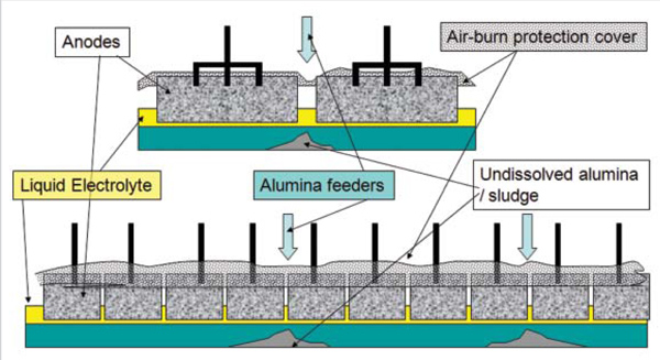
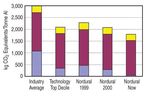
The aluminum smelting process is a strong emitter of CO2 with three major contributions: that arising from electrical energy generation and its utilization, the process conversion contribution linked with anode consumption and anode production, and the greenhouse gas equivalents of the intermittent perfluorocarbon (PFC) emissions. Fundamental studies of alumina solubility, the electrochemical mechanism for triggering the onset of PFC emissions, and the importance of both mixing and current density on the speed of termination of anode effects, help define better paths for process operation. In conjunction with advising prebake aluminum smelters on process optimization, the authors have successfully tested the differences in theory and practice, and applied fundamentals in the operating environment to change some of the installed control strategies, termination mechanisms, and work practices. These changes have improved performance and reduced the CO2 footprint. The overall process reductions achieved exceed 2.24 million tonnes of CO2 equivalents per year in smelters producing less than 3 million tonnes of aluminum per year. INTRODUCTION When aluminum is used in the vehicle and transport sector, the energy and environmental savings it generates far outweigh the energy in its production or the associated emissions that are generated during the smelting.1,2 With the advent of CO2 taxes, however, reducing the CO2 footprint for the production of the metal is of renewed importance. The overall CO2 footprint for production of liquid aluminum has four components:
In contrast, the best available smelting technology at that time had the following figures: those associated with process carbon1.66 tonnes of CO2/ tonne aluminum; the PFC CO2 equivalents 0.35 tonnes of CO2 equiv./ tonne aluminum; for coal-fired power generation14.8 tonnes of CO2 /tonne aluminum; and for natural gas power generation7.5 tonnes of CO2/tonne aluminum. With the different combinations of power sources and technology designs there is a wide spectrum of CO2 footprints of smelters. Since 1990 most of the new technology has been similar to the best available technology but the newer technology only accounts for approximately 50% of the global metal production at this time. In the intervening time there have been closures of a number of smelters that were on the wrong side of the industry average in 1990. However, the present operating technology still has a large breadth of both operating parameters and performances that impact their individual CO2 footprints. This is because the operating conditions are not only dependent on the cell design and the installed control hardware, but also involve subjective judgments on appropriate work practices and actions. With the emphasis on both the return on investment to shareholders and simultaneously being a good citizen environmentally in the global community there is invariably a compromise between:
GREENHOUSE GAS EQUIVALENTS FOR PFC EMISSIONS
As already demonstrated, in some
technologies the PFC emissions
which arise from the co-evolution of
CF4 and C2F6 have a large CO2 footprint.
The International Aluminum Institute
together with scientists from
the industry has determined methodologies
for calculating the equivalent
emissions. Analysis of gas samples
from smelter cells while they are on an
anode effect3 have shown these gases are typically in the range of 1216%
for CF4 and 0.52% for C2F6. PATHS FOR REDUCING CARBON EMISSIONS Reducing the Process Carbon EmissionsThe first of the four sources of process emissions is from the production of the gross anode carbon, which has been shown to generate 0.260.62 tonnes of CO2 per tonne of aluminum for operating smelters.4 The amount depends on baking furnace design, the fuel used to fire the baking furnaces, and the quality control in both the green anode formation and subsequent baking (thus reducing the rejection rate of finished anodes). Unless fuel substitution is possible, the greatest gains in reducing this source of CO2 emission are from reducing the gross carbon consumption value. This requires tight control of cell operating conditions so the final anode butt size is minimized without compromising the metal quality. The second source, electrochemical oxidation of the anode to CO and CO2, accounts for more than 80% of the remaining process gas emissions. As the operating current density is increased the change in the proportion of the two electrochemical products marginally reduces the amount of CO2 per tonne of metal. However, increasing the current efficiency will proportionately reduce the process carbon consumption that occurs via this mechanism when the efficiency loss is via reoxidation of dissolved metal. The remainder of the process carbon consumption occurs through two parasitic side reactions. The first of these is the reaction of the electrochemically evolved CO2 with the anode surface within the pores of the electrode when the temperatures exceed 750°C. CO2 emissions from this mechanism can be reduced by lowering the reactivity of the carbon anodes. The second parasitic contributor is from direct contact between air and the anode surface (airburn) at temperatures above 400°C and this can be minimized by preventing direct access of air to the carbon electrode surface. Achieving Reductions through Reduced Gross Carbon Consumption Because of the intermittent batch operations and limited control of spillage of cover material (used to prevent airburn) into the electrolyte, there is some variation in the liquid electrolyte height. For low gross carbon the anode butts are thin, variation in the electrolyte depth can lead to flooding of the electrolyte over the surface of the anode and corrosion of the steel electrode contact. The metal then has a substantially lower market value. Accordingly, work practices become the dominant mechanism for minimizing gross carbon. Increasing Current Efficiency Although aluminum smelting is a mature industry current efficiency can still be increased since efficiencies as high as 97.5% have been reported for some technologies over short but measurable periods. While it has been well established that reduced current efficiency is influenced by solubility of metal in the cell,5 with improved electrolytes the controlling step for efficiency reduction today is mass transfer of the limited amount of dissolved metal. Turbulence in the metal pad that accelerates the mass transfer of dissolved metal includes the pumping action of large bubbles of gas being released, and waves generated by the magnetically induced circulating metal colliding with piles of undissolved alumina that sometimes form under the metal pad. Thus, contributors to the causes of efficiency lowering include poor anode setting practices and problems arising from the solubility of alumina. Hence, reducing CO2 emissions through efficiency gains requires good work practices and good alumina solubility. Reducing the Parasitic Carbon Oxidation Reactions Protection of the carbon anodes with better covering material (which is restricted to a mixture of electrolyte components and alumina) will reduce air burn. A.M. Fitchett6 studied the fundamentals of the air-burn reaction and demonstrated that the spray coating approach used in many smelters was inadequate by itself, but only a few centimeters of cover material was necessary to inhibit it at all temperatures. She also found that differences in the proportion of coal tar pitch used in the anode production and low anode baking temperatures also contributed to accelerated air burn. S.M. Hume7 extended the fundamental studies of both parasitic oxidation reactions and demonstrated sodium arising from recycled electrolyte was a strong catalyst for increasing the reaction rates. Practically, therefore, the parasitic oxidation reactions can be reduced by better formulation of the green anode mix (to give a low porosity), better cleaning of the anode recycled butts, and more even baking of the anodes at an adequate temperature. Improving anode covering practices for integrity and avoiding spillage into the electrolyte present another option. Reducing the Equivalent Carbon Emissions from Generation of PFCs The PFC emissions arise through concentration polarization of the anode surface leading to co-evolution of CF4 and C2F6 with the normal carbon oxide gases. It has always been assumed that the electrode potential rise at the anode surface needed to be approximately 1V for this to happen since the assumed reaction was Equation 2, and this would have a thermodynamic decomposition voltage of greater than 2.4 V. A more detailed study of the cell gases that evolve from the anode during the approach to an anode effect8 has shown that the formation of the gas COF2 starts occurring for an increase of anode potential of less than 0.3 V above the normal operating level. This can be explained by the independent cell reaction (Equation 3), which thermodynamically should occur at approximately 1.77 V depending on the thermodynamic state of the reactants. The formation of carbon tetrafluoride is thermodynamically favored by a depolarizing chemical interaction with the carbon electrode (see Equation 4). The consequence of this finding is that greater weight should be given to the magnitude of the increase in cell voltage during the underfeeding step in the control system. The magnitude of the rise that needs to be controlled should be small (less than 50 mV). Excessive signal filtering can harm the early detection of this change and therefore the magnitude of the targeted rise is influenced by this limit combined with knowledge of the rate of alumina dissolution. The second consequence of these observations is that, based on the constants used in Equation 1, approximately 50% of the current is carried by the reaction according to Equation 4 with the remainder to cell gas arising from normal CO2 evolution. However, as expected these proportions change with cell design, operating conditions, and technology. Thus it becomes difficult to precisely estimate the actual amount of PFCs being evolved. The importance of early detection of the approach to an anode effect is also highlighted by fundamental studies on anode effects and wetting characteristics.9 There is strong evidence that formation of an intermediate resistive film causes the voltage to increase substantially once the electrode process has changed. Changes in anode wettability at low alumina concentrations have also been shown to increase the anode current density, leading to the onset of an anode effect. Based on this understanding of anode effect mechanisms there are three important areas to focus on in order to minimize PFC emissions. These are:
Alumina solubility has been blamed for many cell operating problems, especially a tendency to increase the anode effect frequency or to cause a consequential lowering of current efficiency. Thus, the authors have had numerous major projects investigating potential causes and interrelationships.1013 From the fundamental perspective it has been found that either heat transfer or mass transfer can be rate determining. The thermal demand for pre-heat of the cold alumina is high and because the electrolyte should only operate at a few degrees above its liquidus temperature; it needs to mix with a large volume of electrolyte if freezing on the surface of the added grains is to be avoided. The amount of heat required for preheat is approximately 0.27 kWh per kilogram alumina added but the endothermic heat of the solution is of a similar magnitude. The cooling that results from absorption of energy from the electrolyte lowers the heat transfer rate and inhibits dissolution. Combining the results of the various solubility studies it is evident that the fastest dissolution rates are achieved when the electrolyte is at the highest possible superheat, has a maximum cryolite composition with a low concentration of dissolved alumina, and the fresh alumina is added slowly in a well-agitated system.14 Within an operating cell the steps that are involved in dissolving alumina are:
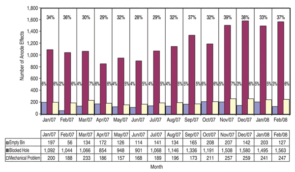
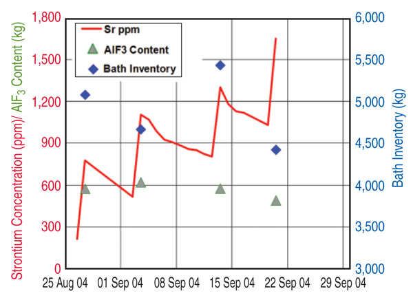
Good dispersion of the alumina powder added to the electrolyte requires the feeder holes to be open and the discharge of alumina is over several seconds. Thus feeder design and volume of the electrolyte in the feed area are primary constraints. However the situation can be improved by work practices that control the total liquid height so that the occasions when there is a risk of formation of hard unbreakable crusts are avoided. The importance of enabling feeder holes to break is illustrated in Figure 2, which presents an analysis of the causes of anode effects in a smelter during implementation. This analysis has been performed in one of the smelters to which the authors have applied control and operating changes. The changes have already resulted in the anode effect frequency reduction by more than 50%. Because of the high thermal demand for the pre-heat and heat of dissolution, each kilogram of alumina added needs to come in contact with 50 kg to 100 kg of electrolyte at the operating superheat before the next shot is added, if temporary sludge formation is to be avoided. Thus, the rate and ability to mix and disperse is crucial. Limiting the overfeed rate to less than 200% (in some smelters it is up to 1,000%) and ensuring the superheat is above 8ºC are practical ways to minimize sludge formation based on the understanding of alumina solubility. Improving Cell Control to Minimize Sludge and Anode Effects The modulation of the alumina concentration in the electrolyte between two assumed limits generates a characteristic voltage-versus-time curve that should prevent the onset of co-evolution of the PFCs. It is based on the variation in voltage with alumina concentration as predicted15 through the combination of changed electrical conductivity, electrode polarization, and Nernst potential. The shape of the curve is dependent on operating current density, inter-electrode distance, and the electrolyte composition. Practically, distortions and superimposed noise occur on the control curve because of the dynamics of the metal and electrolyte flow in the cell and fluctuating resistance from the gases evolved. Consequently, it is common for the raw signal to be filtered prior to analyzing. These features introduce some uncertainties and time lags while the control system is further complicated by assuming constant electrolyte volume in the cell; the amount of alumina discharged from the hopper (volumetrically but assumed gravimetrically) dissolves in the electrolyte before the next addition; the added alumina is uniformly distributed within the cell; and the rate of depletion in alumina through the modulation is linear with a rate proportional to the magnitude of under or over feeding. Recent studies,16 however, have shown there are several weaknesses in these assumptions. These include the electrolyte volume in a cell varying by up to 30%16 (see Figure 3); the alumina concentration is seldom distributed uniformly throughout the cell;13 not all the alumina is transferred at the rate expected from the hopper to the electrolyte;17 and, in some instances the overfeed rate exceeded 400% for up to four minutes whereas the maximum feed rate that can be sustained based on alumina solubility and optimum conditions is 200% for two minutes. Improved Detection of the Underfeed Duration Limit Indicators of approaching the lower concentration limit (which needs to be set above that required for anode effect) are: an increase from the minimum voltage achieved just after the overfeed sequence; achieving a designated slope for the rate of change in voltage with time based on the assumptions and feed rates; the second derivative of the rate of change in voltage with time (the latter being to ensure it is on the positive side of the voltage rise curve); or achieving conditional combinations of some of these options. Because of the process dynamics each of these has some limitations. However, the first indicator has the greatest scientific rigor and is less subject to process variations. Despite this, it is usually the second or the second in combination with the third option that is most commonly used. Optimizing the detection limit combinations for a given design and operating conditions, or modifying the trigger values, present options for improving the lower limit of control to minimize anode effects. The authors experience has found that the least weight should be given to the second derivative approach because of its extreme sensitivity. Reducing the Anode Effect Duration While it has received much less attention than reducing the anode effect frequency, reducing the anode effect duration has a similar proportional effect of reducing the equivalent CO2 emissions from PFCs. The theoretical understanding of the cause of anode effect (oxide concentration polarization) points to four options for terminating the anode effect. These are: reducing the current density, increasing the alumina concentration, shorting the anode to the metal pad for chemical cleaning, and improving the wetting characteristics between the electrolyte and electrode. Most smelters work on a combination of the second and third options, and use excessive alumina replenishment feed ratesadding enough to increase the total alumina concentration by 1% within two to four minutes. This far exceeds the rate at which it can dissolve and invariably results in sludge formation and slower termination. Contrasting the initial movement of the anode beam goes in the wrong direction for quick shorting and current density lowering as it usually starts with an up movement and has numerous built-in pauses before achieving the required magnitude of downward movement. Consequently, the theory points to the best practical way of reducing anode effect duration being to reduce current density and promote shorting faster by a more substantial downward beam movement. There is less need for aggressive alumina feeding
Because of pre-designed hardware constraints not all options could be implemented at each smelter, while there were neither major capital investments nor significant design changes. In presenting the contributions to the achievements the data from two smelters is not included in order to ensure anonymity and protect priority of knowledge. A Case Study in an Individual Smelter The details of the approach taken at Nordurals Icelandic smelter have been described in a series of publications.18,19 Key changes made included:
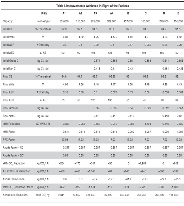
Although improving the current efficiency and reducing energy consumption were less important for this smelter because of the combined hydro and geothermal energy sources, contributing gains were achieved, making the operation more competitive. Overall Improvements in the Study Group Table I summarizes the more relevant performance indicators that impact the CO2 footprint. Both the initial values and the values achieved when the smelters were running under their optimum conditions are tabulated for eight of the potlines included in the improvement program. The selected grouping represents an annual production of 1.89 million tonnes of metal. The approach used for efficiency gains and reduction in equivalent CO2 greenhouse gas emissions was different for each potline because of constraints or design differences. However, they generally included the various features highlighted and the introductory comments, and especially the application derived from the thesis findings. Reduction in anode effect duration was applied in this group, which also brought about major gains. The magnitude of the reduction achieved in the various potlines varies from 620 kg per tonne of aluminum to more than 2 tonnes of CO2 equivalents per tonne of aluminum. This data represents a good cross section of the worlds technologies and power sources used by the smelting industry:
CONCLUSION
The initiation point for each of the
variables changed in the smelter operations
was triggered as a consequence
of fundamental academic studies at the
University of New South Wales and
University of Auckland over the last
30 years. All the Ph.D. projects cited
were funded from industry grants with
the smelters receiving the data. Implementation
of changes in smelters, however,
has been slow because many of
the changes went against conventional
thinking or operating practices.
ACKNOWLEDGEMENTS The achievements cited draw on the experimental ingenuity and intellectual input of many outstanding doctoral students who worked on the various projects. The practical implementation necessitated assistance and dedication of many operating process engineers, while the willingness of their managers to take the risks was another vital part. However the payoff has been immense. REFERENCES
1. H.N. Han, The Environmental Impact of Steel and
Aluminum Body-in-Whites, JOM, 48 (2) (1996), pp.
3339.
Barry Welch is a part-time visiting professor at the University of New South Wales as well as an industry consultant; Martin Iffert is managing director at Trimet Aluminum AG; and Maria Skyllas- Kazacos is Professor Emeritus of Chemical Sciences and Engineering at the University of New South Wales, where she continues to supervise research in aluminum reduction. Dr. Welch can be reached at barry@barry.co.nz. |