|
In connection with the 125th anniversary
of the HallHéroult process
this year, we will review the most important
progress that has been made
in the twentieth century. What were
the most significant improvements in
this period, and which scientists and
engineers came up with the ideas for
these improvements? In this paper we
will try to answer these questions. We
will highlight the major technological
breakthroughs and mention those people
who played important roles in the
development of these improvements.
INTRODUCTION
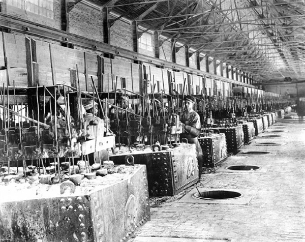
This year is the 125th anniversary of
the invention of the industrial aluminum
electrolysis process. The first 20 to
30 years after 1886 were characterized
by many technological improvements in the process, but we will start our review
from 1914, the year when both the
inventors Charles Hall and Paul Héroult
passed away (Figure 1).
First, we must conclude that this is
a very good method, because it has
survived the many attempts that have
been made to develop a viable alternative
method for production of aluminum.
Throughout these years aluminum
production has developed from
"art" to "science." A steadily increased
understanding of the process has been
achieved thanks to extensive research
and development work, both in aluminum
plants and in universities and academic
institutions around the world.
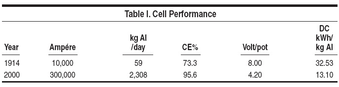
Breakthrough inventions in aluminum
smelting during the past 125 years
have resulted in amazing gains in cell
performance, as demonstrated by the
jump in amperage and aluminum production
in modern cells, (+2,249 kg Al
per cell day) compared with the production
per cell in 1914, as well as a 60%
decrease in the specific energy consumption
(Table I).
20th CENTURY
INVENTIONS AND
BREAKTHROUGHS
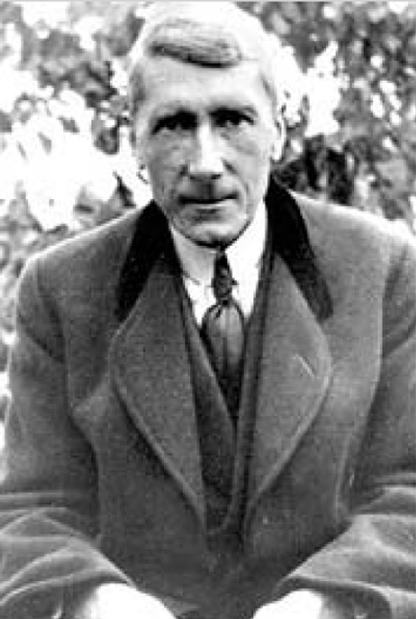
The Søderberg Anode
The first big improvement, named
after the Norwegian inventor, is the
Søderberg anode. Carl Wilhelm Søderberg
was born in Sweden, but moved
to Norway with his parents as a small
child (Figure 2).
The Søderberg anode was patented in
1918 and it has been used in the aluminum
industry since 1923. By this time
prebaked anode pots had been in service
for almost 40 years. What makes
the Søderberg electrode unique is that
it is continuous, self-baking, and monolithic.
The lower part of the anode reacts
during the electrolysis process, and
in the upper part addition of "green" anode
paste briquettes gradually replaces
the anode material that is consumed at
the bottom surface. The heat from the
electrolyte gives the bottom of the anode
the right baked consistency.
The studs in the Søderberg anode
are usually placed vertically, but also
horizontal stud Søderberg pots have
been developed. Even now there are
still some horizontal stub Søderberg
potlines in operation. The so-called
"Erftwerk" pots were developed in the
1950s by Vereinigte Aluminium Werke
(VAW). The Elbewerk smelter in Germany
started up in 1972 and was operating
until 2006 at about 130 kA. These
pots had continuous prebaked anodes,
which still seems to be a good idea.
However, these potlines are now closed
for good.
The main advantages of vertical stud
Søderberg pots are that they save the
capital, labor, and energy required to
manufacture prebaked a nodes. These
pots have some inherent disadvantages,
however, compared to prebake pots.
Pot voltage and energy consumption
are higher for Søderberg pots, current
efficiency is lower, anode quality is
lower, and emissions of fluorides and
polycyclic aromatic hydrocarbons
(PAH) are higher. Also the pot size is
smaller, especially compared to modern
prebake pots.
A breakthrough improvement of
Søderberg pots came in the late 1970s,
when the Sumitomo aluminum company
marketed and sold their Søderberg
pot technology. This mainly consisted
of "dry" anode paste with lower pitch
content and introduction of bar breakers
or point feeders for alumina addition.
These improvements lowered the
PAH emissions and made feeding the
pot easier. However, in the beginning
there were a lot of operational problems
for those smelters that chose to implement
this Sumitomo technology.
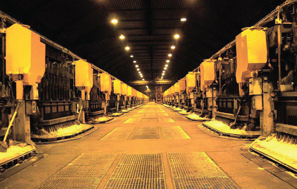
More recently, successful and valuable
improvements have been reported
in Søderberg pot design and operation
in some countries, mainly in Norway
and Russia. Measures were taken at
Elkem's plant in Lista, Norway (A.K.
Syrdal and T.B. Pedersen) in the 1990s
to improve current efficiency and energy
consumption, as well as the environmental
performance by better alumina
feeding technology (point feeding) to
reduce the frequency of anode effects
and the greenhouse gas emissions, and
by introducing a closed anode top to
nearly eliminate the PAH emissions
(Figure 3).1 In the Krasnoyarsk plant
in Russia different methods for hooding
and sealing of the pots have been
developed, and a colloidal anode with
pitch content close to that of a prebaked
anode, has been tested.2 This "breakthrough"
technology was directed by
Victor Mann and Vladimir Frizorger
(project creators and leaders) and
conducted by Mikhail Krak, Nikolai
Tonkih and Matei Golubev (carbon
technology managers) at UC RUSAL's
Engineering and Technology Center
(ETC) in Krasnoyarsk.
Thus, it is too early now to conclude
that "The Søderberg Era" is completely
over.
As a curiosity it can be mentioned
that in spite of his success with the
Søderberg electrode, it was building of
violins that was Carl Søderberg's great
interest in life! He built about 30 of
these instruments.
Point Feeding of Alumina
The next big development to occur
was the use of point feeders in the
early 1960s at Alcoa. The point feeder
development did not start as a process
improvement effort but instead it was
strictly a labor saving opportunity. Prior
to this development all the alumina
was fed manually in rather large quantities
(~100 kg) several times per day.
In the end the process improvement advantages
greatly outweighed the labor
savings.
In 1961 one of the Alcoa smelters in
the United States (Rockdale, Texas)
used point feeders that are still in common
use without any design changes
today.3 This feeder was developed in
the Alcoa Equipment Development Division
(AEDD) at Alcoa Laboratories
in New Kensington, Pennsylvania as a
collaborative effort and resulted from
the unsuccessful effort by several individual
plants to make a labor saving
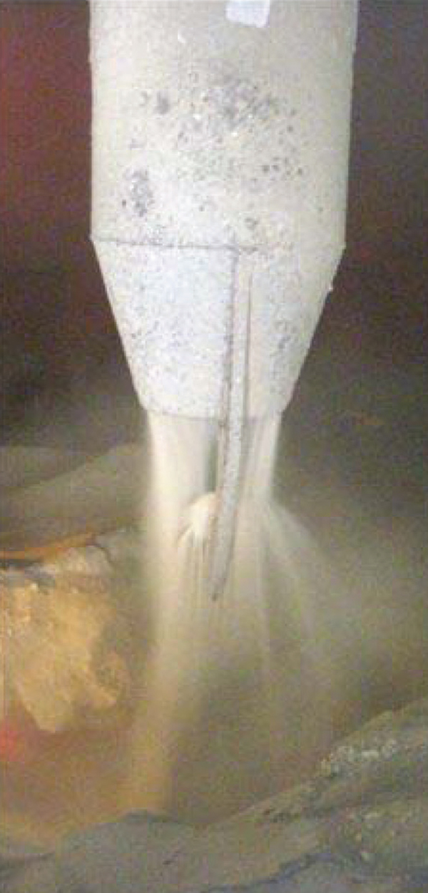
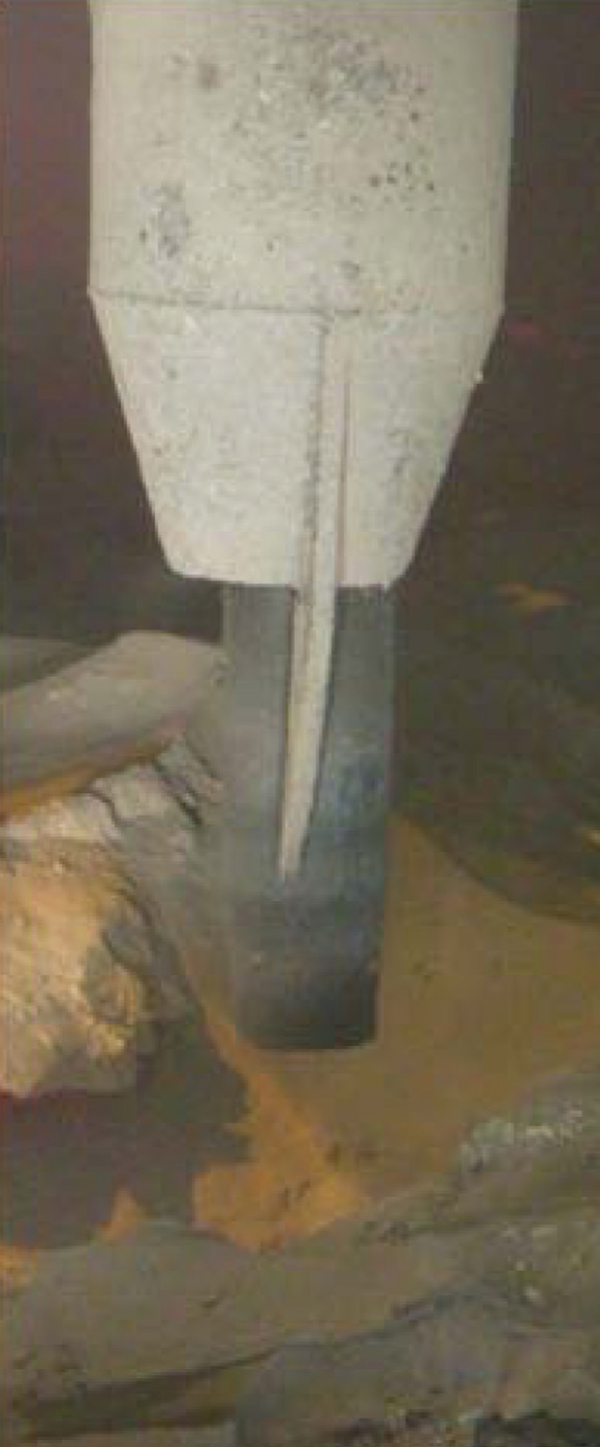
feeder. The first of the early feeder designs
dates back to 1958 and some are
still running at the Alcoa Wenatchee
plant (Figure 4).
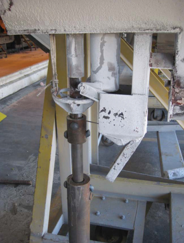
These early feeders were not as reliable
as the AEDD feeder (Figure 5).
The key person in the point feeder development
was Dick Taylor. However,
nobody outside of Alcoa has ever heard
of him until now!
All modern pots now have point
feeders. The method consists of punching
small holes in the crust at two to six
positions (usually) along the center line
of the pot. The feeding is done with single
piercing rods, between six and ten
centimeters in diameter. These rods are
mounted at the end of fast-acting pressurized
air cylinders. The great advantage is that small quantities of alumina
are added to the electrolyte at each
break-and-feed. This method generates
minimal sludge formation in the center
area of the pot, and there are minimal
emissions of dust and fluorides during
the break-and-feed operations.
The point feeder represented a real
breakthrough, also literally speaking,
in the alumina feeding technology. One
may safely say that the point feeding
technique is one of the most important
inventions in the HallHéroult
pot technology in the last century.
Although there are some detail differences
in how the various companies
designed each of their point feeders
(just as there are design differences
in the pots), the basic principle of this
technology has remained unchanged
since its inception, much the same as
the HallHéroult process.
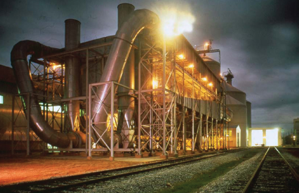
Gas Cleaning by Dry Scrubbing
The third main improvement of the
last century was treatment of the pot
fume with dry scrubbers. The development
was motivated by the need to
protect the environment to a greater
extent than could be obtained by the
wet scrubbing technique that was being
used. The dry scrubbing process
is now used in almost all aluminum
smelters in the world. One great advantage
of dry scrubbers compared to
the older wet scrubbers is that they use
the raw material alumina as the sorbent
for removal of gaseous and particulate
fluorides from the anode gases. The fluorides
are chemisorbed on the surface
of the alumina particles, which are then
called secondary alumina. This material
is stored in large silos and is later
used as feed material to the cells. This
means recycling of the captured fluorides
and it thereby reduces the overall
fluoride consumption significantly.
Environmentally, the dry scrubber process
has been instrumental in reducing
the fluoride emissions from aluminum
plants.
The process was developed by Alcoa
(alumina fluid bed technology) and Alcan-
ÅSV (alumina injection scrubbers)
in Norway in the late 1960s. The earliest
recorded report on this development
at Alcoa was February 23, 1965exactly
79 years after Hall's invention.
This was a collaborative effort done in
Alcoa's Physical Chemistry Division
at Alcoa Technical Center. In terms of
the development of the dry scrubbers
there is a dual credit. Lester Knapp
and Norman Cochran were the key
persons in this development for Alcoa.
The first commercial injection type dry
scrubber system was installed by ABB
Flakt at the VSS smelter Granges Aluminium,
Sundsvall, Sweden in 1972
with separate reactors followed by cyclones
and bag filter. The first prebake
injection type (alumina injection into
the branch duct leading into each filter
compartment) dry scrubber system was
installed in 1973 by ABB Fläkt (Erik
Monkerud was project manager) at the
HAW smelter in Hamburg, Germany.
Figure 6 shows the Alcoa 398 reactor
at Badin from 1971. They were mixing
pot gas with alumina, there were
integrated filters and they recycled the
material back to the electrolysis cells.
Nearly all new aluminum smelters today
are built with dry scrubbers using
alumina injection technology.
REDUCING FLUORIDE
EMISSIONS TO THE
POTROOM ROOFLINE
The major sources of fluoride emissions
into the working atmosphere and
to the potroom roofline are from pots
with open hoods and from hot anode
butts pulled from pots during the anode
change operation. Two recent breakthrough
inventions have to a large degree
solved these environmental problems.
The first was the development of
on-demand dual duct suction systems
to nearly double extraction flow rate
during active pot work, and the second
was the development of anode cooling
boxes that collect the HF emissions
from hot bath and anode butts. These
two inventions have resulted in a sharp
reduction in HF emissions to the potrooms
roofline.
The normal duct suction velocity is
inadequate to contain the fluoride gases
from pots when the hoods are open
during anode changing. The solution to
this problem was to increase the duct
suction velocity by a factor greater than
two using a dual duct system. The first
two industrial applications of the dual
duct system were at the Alcoa Deschambault
smelter in the fall of 2002,
which increased the duct flow from 864
to 1,584 Nm3/h during anode change
operations,4 and the Hydro Sunndal
smelter in Norway also in 2002, which
increased the normal duct suction of
5,000 Nm3/h to 15,000 Nm3/h during
anode change operations.5
Emissions from hot anode butts
and crust account for 35% of the total
fluoride emission in potrooms. The
majority of HF emissions from hot
anodes occur during the first 20 minutes
of cooling. The solution to this
environmental problem was to put the
hot anodes inside cooling boxes. In
1999 Gilles Dufour began the design
and development of prototype anode
cooling boxes and crust bins and were
implemented in 2000 at the Alcoa Deschambault
smelter in Quebec, Canada.6
The use of cooling boxes that contain
the fluoride gases resulted in a 35%
reduction in HF emissions to the potroom
rooflines at Deschambault. Stig
Lægreid of Hydro Aluminium developed
anode butt cooling boxes that are
connected to the plant fume duct system
to collect the fluoride gases from
hot bath and anodes taken out of pots.
The first section of HAL250 cells were
started in October 2002 at the Sunndal
smelter in Norway.5 By the use of the
special dual duct gas collection system
and anode cooling boxes, the fluoride
emissions are very low at Sunndal, less
than 0.35 kg F/t Al, to meet environmental
regulations (both OSPAR and
local conditions). The dual duct system
is now standard installation at new
modern aluminum smelters.
Introduction of Computers for
Cell Control
The underfeed-overfeed alumina
control is another key breakthrough in
the operation of aluminum pots. The
advent of process control for manufacturing
process was in the 1960s but only
involved resistance control procedures.
The initial concept of underfeed-overfeed
alumina in aluminum pots was
first perfected by Dr. Warren Goodnow7
at Kaiser Aluminum in 1974. The demand
feed strategy determines the rate
of alumina addition to a pot, based on
line amperage and pot voltage signals.
The notion of a demand to feed a higher
rate of alumina is based on the observation
that the cell resistance rises
as the bath is depleted of alumina prior
to an anode effect (Figure 7).
Kaiser Aluminum was also the first
company to develop and commercialize
a distributed microprocessor
computer automation system, called
Celtrol, for controlling the pot operating
voltage and alumina feed to aluminum
pots using the demand feed
strategy. Celtrol was invented by Steve
Price and Charlie Nemeyer (software),
Mark Kafel (hardware) and later Terrel
Wright at ASG in Spokane. It was
very successful in upgrading older aluminum
smelters to improve pot performance and minimize environmental
emissions by reducing the occurrences
of anode effects. The Celtrol computer
system was used extensively in all Kaiser
aluminum smelters as well as in
many international smelters.
Bath Chemistry Changes
Baths with High AlF3 Contents
Alcoa was probably the first company
to realize that higher AlF3 concentrations
in the bath could give higher
current efficiency. In the Wenatchee
smelter in 1954 the AlF3 concentration
was increased from 1.5 to 6% excess
AlF3, and the current efficiency went
up 3%, from 84.8 to 87.9%. Thomas
Holmes did the first industrial tests with
high bath acidity in the 1950s.3 Further
work was done in Badin in 1965, where
a test at 11% AlF3 was done in P-155
pots. However, the test was a failure,
which has been vividly described by
Holmes himself.6 The AlF3 concentration
was then increased much too
fast, the pots lost their protective side
ledge and "they tapped out faster that
we could patch them," to use his own
words. This was a serious setback and
it was 11 years later, in 1976, that operation
at 11.5% AlF3 in the Badin cells
gave 91% CE.
Mathematical Models for
Magneto Hydrodynamic
Calculations
Many companies have developed
their own mathematical models for calculations
of the magnetic fields in their
pots. Undoubtedly, MHD design has to
rank high on the list of great inventions
in the 20th century. Robert F. Robl of
Alcoa was doing this by hand and with
a physical model prior to computers.
Alcoa started to understand this in the
early 1950s with design of pots with
side-by-side orientation and quarter
point anode risers, instead of the usual
end-to-end pots with end risers. Big
pots (>100 kA) probably would not be
very practical without this.
Important advancements were made
in the development of MHD models
in the twentieth century. These led to
retrofitable changes in the pot bus-bar
designs in existing aluminum potlines
of older pot technologies that substantially
improved the MHD behavior
and consequently the pot performance
effi ciencies. First, magnetic compensation
technology was developed by
Vinko Potocnik (Alcan), Wolfgang
Schmidt-Hatting and Jacques Antille
(Alusuisse), Marc F.G. Jouget and
Jean P. Givry (Pechiney) in the 1950s
and 1960s, and Thorleif Sele and Hans
Georg Nebell (Hydro) to convert endto-
end prebake and Soderberg pots with
compensating three-riser asymmetric
bus to reduce the high Bz fields associated
with the closeness of the adjacent
row of pots in the same potroom. This
made it possible to dramatically increase
the potline current without a loss
in current efficiency.
Later, Nobuo Urata (Kaiser), Detlef
Vogelsang, Christian Droste, and
Martin Segatz (VAW), and JeanPierre
Dugois and Paul Morel (Pechiney) developed
the MHD modeling capability
to retrofit the end-riser Kaiser P69,
Pechiney AP13 and Reynolds P19 prebake
cells with magnetically compensated
bus-bars under the pots in order to
reduce the high Bz associated with the
high current flow around the ends of the
pot, subsequently making it possible to
increase the potline current.
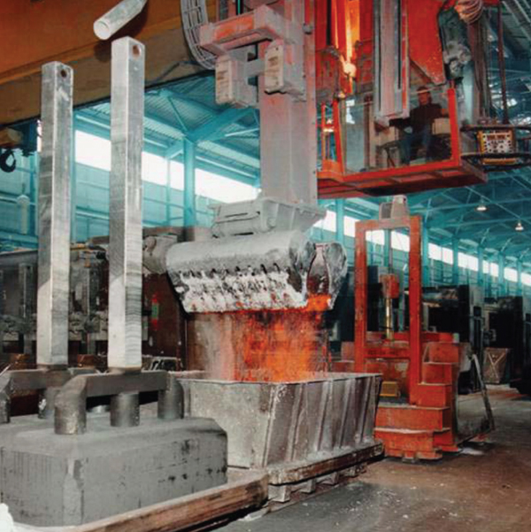
Large Pot Development
(High-Amperage Potlines)
The size and amperage of Hall-Héroult pots have steadily increased in
the twentieth century. Typical pot size
was about 50 kA in 1940, compared to
10 to 20 kA pots in 1914. In 1963 Alcoa
had a potline in North Carolina running
at 155 kA and in 1969 Alcoa had a 225
kA potline in operation in Tennessee.
These 225 kA pots had individual elevation
adjustment of anode pairs, because
it was then believed that this was
necessary for operation of so large pots.
Later experience has shown that this
was unnecessary. The Høyanger 220
kA potline was started in 1981 with a
fixed anode bridge.
The AP18 prebake cell is well-known
as being the first modern prebake cell.
The project was led by Eric Barrillon
and Gerard Hudault. The cell was originally
designed by JeanPierre Dugois
and Pierre Homsi (busbar modeling),
Paul Bonny (computer control system),
Jean-Louis Gerphagnon (cell hardware
and construction), using extensive
state-of-the-art magnetic and thermoelectric
modeling. In 1976, Aluminium
Pechiney's Laboratoire de Recherches
des Fabrications (LRF) started up the
first four prototype AP18 prebake cells
operating at 175 kA, and in 1979 they
installed 60 AP18 cells in potline F at
St. Jean-de-Maurienne, France. The
first commercial potline of AP-18 cells
was started at Fort William, UK in 1981.
Later this type of cell achieved a record
operating performance of 95% current
efficiency and 13.3 DC kWh/kg Al at
180 kA.8
The next major advancement in cell
technology was the development of
the +300 kA superpots. The first cells
to operate above 300 kA were the Alcoa
A817 and the Pechiney AP30 cells.
In 1978 Alcoa was running a pilot cell
at its Massena, NY smelter at 280 kA.
This was the basis for the Alcoa A817
pots that were installed at the Portland,
Australia plant. Construction of the
Portland plant started in 1980 but due
to an economic downturn the construction
was delayed and the two potlines
with a total of 404 pots operating at 300
kA did not start until 1986. There were
initially extensive operating problems
with the pot that did not get solved until
a magnetic retrofit in 2002. No other
potlines of this type were ever built due
to the operating problems (Figure 8).
At nearly the same time the Pechiney
AP30 pot was developed at St. Jean-de-
Maurienne which also operated above
300 kA. The project was led by Maurice
Keinborg, Jean-Louis Gerphagnon
and Bernard Langon. The cell was originally
designed by Jean Pierre Dugois
and Pierre Homsi (bus-bar modeling),
Benoit Sulmont (computer control system),
Christian Duval (cell hardware
and construction) and Bernard Langon
(operations). New pot technology
inventions developed for the AP30
cell include forced-air cooling of the
cathode shell using localized jets, and
detection of the bath level via chisel
stroke.
The AP30 cell technology era began
in 1981 with the development of cells
operating at 280 kA, which was industrialized
on potline G of 120 AP30
cells started up in the Saint-Jean-de-
Maurienne, France in 1986. In 1991
the Dunkirk smelter with 264 AP30
cells was started at 293 kA, and is now
reported to be operating beyond 360
kA. The most recent technology breakthough
was the development of AP50
(500 kA) prebake cells that was started
by LRF in 1989 at Saint Jean de Maurienne.
This represents a jump of 200 kA
higher than the previous generation of
AP30 cells.
HIGH AMPERAGELOW
ENERGY CONSUMPTION
POT TECHNOLOGY
A recent breakthrough invention has
been the development of high amperage
aluminum pots, 400-500 kA, that operate
at low specific energy consumption,
12.500 DC kWh/kg Al. Due to the
high cost and decreasing availability of
electrical power in China, Northeastern
University Institute (NEUI) has developed
a family of high-energy-efficiency
pot (HEEP) technology. This family of
400 kA aluminum cells operates stably
and effi ciently at 3.85 volts and 12.50
DC kWh/kg Al.9 The operating amperage
of NEUI400 HEEP pots actually exceeded
the amperage indices, for example:
Henan Zhongfu Industry Co. (415
kA), Linfeng Aluminium Industry and
Power Co. (440 kA), Shandong Nanshan
Aluminium Co. (430 kA) and Jinning
Aluminium Co. (460 kA). NEUI is
also developing a family of NEUI500
(500 kA) pots that will also operate at
3.85 volts and 12.500 DC kWh/kg Al.
To operate at the low anode-cathode
distances and energy values the HEEP
pots have low anode current density, as
well as improved magnetic and thermal
designs. The NEUI 300 and NEUI 400
prebake project is directed by Mr. Lu
Dingxiong and Mr. Liang Xuemin. The
development of the busbar arrangement,
magnetic fluid stability technology
and thermal design was completed by Mao Jihong, Mr. Qi Xiquan, Mao
Yu, and Ban Yungang. The computer
control system was developed by Wang
Dequan and Qi Xiquan.
New Cathode Materials
Initially all aluminum electrolysis
pots had a monolithic carbon cathode
lining that was installed manually by
ramming a plastic paste into place. Prebake
cathodes first appeared in pots at
St. Jean-de-Maurienne, France in the
1920s. From the 1950s to 1970s there
was a gradual conversion by aluminum
companies to use prebaked cathode
blocks with rammed paste in joints and
seams. Since the 1970s there has been
an increase in the added graphite content
(semi-graphitic) in cathode blocks
in order to reduce the electrical resistance
of cathode blocks and thus allow
a reduction in specific energy consumption
of cells. The first major manufacturers
of cathode blocks for aluminum
pots were Great Lakes Carbon and
Union Carbide Carbon companies in
North America, as well as Sigri and
Carbon Savoie companies in Europe.
Sumitomo Corporation was the first
company to manufacture and commercialize
fully graphitized cathode blocks
for use in aluminum cells. The brand
name was SK-Block, where "S" was
coming from Sumitomo and "K" coming
from Kyowa Carbon, the original
developers, and it has been known for
about 30 years throughout the industry.
Graphitized cathode blocks provide
significant energy savings in aluminum
pots due to its unique high electrical
conductivity. It was initially employed
in the conversion of standard wet paste
VS Søderberg pots to the "Sumitomo"
dry anode paste Søderberg technology
in the 1980s. But in recent years
graphitized cathode blocks have proven
to be especially successful in reducing
the cathode voltage drop in modern
prebake pots, thus allowing smelters
to increase the potline amperage even
higher.
The introduction of silicon carbide
bricks for sidewalls came about as a
result of the increasing potline amperage.
The plants needed to reduce
the sidewall insulation to increase the
heat loss through the sides of the pot
and thereby maintain a protective side
ledge of solid cryolite. SiC had similar
thermal conductivity to carbon and was
a good choice because it also provided
a silicon tracer for sidewall attack. It
is used in most modern pots now. The
first major producers of high grade
silicon-nitride bonded silicon carbide,
which has a higher chemical resistance
to molten cryolite, were Carborundum
and Norton refractory companies in the
US and later Annawerk in Germany.
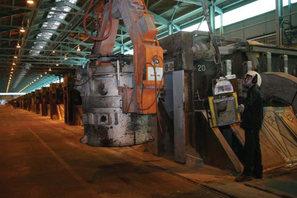
Pot Tending Machines
The cranes in the potlines have indeed
become increasingly more sophisticated.
In addition to include the
cavity cleaning scoop, modern cranes
can be equipped with a pneumatic driven
punch for crust breaking and a bin
and a feed spout for the alumina-bath
mixture that is used to cover the newly
placed anodes. Alternatively, pot tending
motorized vehicles can be used for
anode changing and also for metal tapping.
Although aluminum production
is still labor-intensive, these improvements
have greatly reduced the need
for heavy manual work for the operators
and exposure to dust and fluoride
fumes.
Large multi-purpose potroom cranes
became necessary only after the construction
of large modern high-amperage
aluminum pots due to their use of
very large and heavy anodes, as well as
larger aluminum tapping crucibles for
the increased aluminum production.
However, potroom cranes are no longer
required to add alumina to ore bins on
pots, as this can be done by air slides
and dense phase transport of alumina.
ECL in France has been supplying
cranes to the primary aluminum industry
since 1947 with 1,000 PTM in operation
in potrooms, and with addition
furnace tending assemblies and cranes
in the carbon plant and cast house. ECL
was created in 1947 in Lille by Robert
DeBuire, a mechanical structure
engineer, Joseph Tella, an electrical
engineer and Daniel DuClaux, a mechanical
engineer. NKM Noell Special
Cranes in Germany has been working
closely together with aluminum companies
for more than 40 years and has
now more than 1,000 cranes in operation
worldwide.
ECL invented the pacman, or clam
shell device, that is used by crane operators
to clean large pieces of crust
and carbon out of the bath in pots when
changing anodes. It was not implemented
in the AP18 technology until
some plants were experiencing an excessive
number of anode spikes. The
pacman was first installed in the AP18
potline at the Karmøy smelter in 1985
(Figure 9).
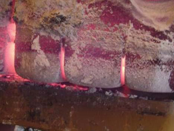
Slotted Anodes
The smelter in Deschambault, Quebec
was the first to use slots (with
very small slot depths) in anodes to
stop cracking anodes. The idea was
that these small slots would act to stop
crack formation. Ron Barclay was the
Alumax carbon expert trying to solve
the anode cracking problem. However,
they stopped using slots once they
solved the cracking problem, and they
then were not realizing the value and
the effect of the gas bubble removal
from the underside of the anodes.
The Alouette smelter in Quebec was
experimenting in making "huge" anodes
for their AP30 pots to combine
two anodes into one anode. They found
out that this dramatically increased the
voltage drop and pot instability, and
thus they went back to the "regular"
size anode, but put small slots in it to
reduce the voltage drop.
At about 1996 Eric Lavoie and Luke
Tremblay from Reynolds' Baie Comeau
smelter visited the Alouette smelter
and recognized the value of slots in the
anodes. Reynolds then started working
at optimizing these slots, how many
slots that were needed per anode, and
how deep the slots should be. Xiangwen
Wang from Reynolds made measurements
in 1998-1999 on the current
distribution, etc., on anodes at Baie
Comeau and developed specific recommendations
on the number of slots and
the slot depth to achieve the maximum
benefits of slots. Baie Comeau adopted
Xiangwen Wang's recommendations
and implemented equipment to "cut
slots with circular saws". All anodes
used in all AP-18 potlines at Baie Comeau
had slots (Figure 10). As a result
they achieved a minimum voltage reduction
of 50 mV on all pots, and they
were able to increase the amperage by
10 kA.
Thus, Baie Comeau was the first
plant in the world to successfully implement
slotted anodes in all potlines
in order to increase potline amperage.
Erik Trembley was the offi cial slotted
anode concept man, and Xiangwen
Wang was the official person that got
the science right!
Increased Amperage in Existing
Pots
Previously, the pots were designed
for a given amperage, and that amperage
was the target, if they could reach
it. Increased amperage in existing pots
has obvious advantages. This is why
many aluminum producers have increased
the amperage in their potlines
in the last 20 to 30 years.
An example is the retrofitting and
modernization of older 150 kA end-to-end pots that have made it possible
to operate some of these pots at above
200 kA. Some end-to-end potlines
have now even reached 220 kA. These
are indeed impressive results. It is really
surprising how much improvement
has been achieved here, and for some
potlines it has been possible to increase
amperage with more than 30 to 40%,
and even up to 50%. Economically this
has been one of the success stories for
many aluminum smelters.
CONCLUSIONS
The potlines have indeed become
a safer working place in the twentieth
century. This is mainly due to increased
awareness and attention about safety
and risk-based management, and workers'
health and safety have become
key elements in modern management
philosophy. Introduction of automatic
alumina breakers and feeders has had
a great influence on safety by reducing
the manual work. The PTM equipment,
and especially the scoop for cavity
cleaning, has reduced the need for
operators working on the floor during
anode change.
The environmental problems have
shown remarkable progress. The fluoride
emissions from the smelters were
a huge pollution problem in the past,
and the invention of dry scrubbers is
perhaps the greatest contribution to improved
environmental protection. The
fluoride emissions are now reduced to a
fraction of what they were before 1960.
Other improvements came later, after
1990, with the increased awareness of
perfluorocarbon emissions from anode
effects as significant contributors to the
greenhouse effect. Present emissions
are now only about one-tenth of what
they were before 1990.
Energy reduction has been huge,
from 40 to 13 kWh/kg Al during the
twentieth century. The main contributor
has been lower pot voltage in all
parts of the pots, together with improved
current efficiency.
In the twentieth century the understanding
of the fundamentals of the
Hall-Héroult process have indeed been
increased significantly. Here we remember
the Boudouard reaction, where
carbon reacts with carbon monoxide to
form carbon dioxide, and the Pearson-Waddington equation for calculation of
current efficiency from the ratio of carbon
dioxide to carbon monoxide in the
anode gas. However, in the technology
of the process the only invention that
has been given the name of its inventor
is the Søderberg pot.
In spite of the fact that there are still
many unsolved problems, we have indeed
come a long way since the days
of Hall and Héroult. Our paper pays a
tribute to those who have contributed
to make the Hall-Héroult process safer
and environmentally cleaner, as well as
making it a more energy efficient and
profi table process.
The past century was full of remarkable
discoveries, developments, and
achievements for the industry. But what
will shape our industry in the future?
Will it be drained cathode, huge kA,
inert anode, carbothermic, low temperature
electrolysis, organic electrolytes?
Will it be dominated by materials
development, sensor development/
control, etc.? What impact will SO2 and
CO2 regulations have on production
methods and smelter location? What
impact will the public's insatiable appetite
for electric power (e.g., electric
cars) have on the industry energy cost
and location of smelters (e.g., stranded
power locations)? Or, will aluminum
smelters thrive in areas of high population
by becoming the best friend of
power companies as "surge capacitors"
for electric grids? Indeed, with these
possibilities, the future of our favorite
metal is as bright as the metal itself!
ACKNOWLEDGEMENT
During the writing of this paper the
authors have received valuable information
from several people. We would
especially like to thank Jay Bruggeman,
John Johnson, Olivier Martin,
Tor Bjarne Pedersen, Michel Reverdy,
Jomar Thonstad, Geir Wedde, and
Siegfried Wilkening for their kind interest
and help.
REFERENCES
1. T.B. Pedersen, A.K. Syrdal, and A. Saethre, Light
Metals 1995, ed. James W. Evans (Warrendale, PA:
TMS, 1995), pp. 253256.
2. V. Mann, Light Metals 2006, ed. T.J. Galloway
(Warrendale, PA: TMS, 2006), pp. 181183.
3. T. Holmes, Light Metals 1995, ed. James W. Evans
(Warrendale, PA: TMS, 1995), pp. 371373.
4. S. Broek, N.R. Dando, S.J. Lindsay, and A. Moras,
Light Metals 2011, ed. Stephen Lindsay (Warrendale,
PA: TMS, 2011), pp. 361367.
5. J.A. Haugan, A.H. Husøy, and K.ø. Vee, (Presented
at the TMS 2003 Annual Meeting, San Diego, CA,
March 36, 2003).
6. J-P. Gagne, R. Boulianne, J.-F. Magnan, M.-A.
Thibault, G. Dufour, and C. Gauthier, ed. T.J. Galloway
(Warrendale, PA: TMS, 2006), pp. 213217.
7. W. Goodnow, US Patent 3,812,024, 1974.
8. M. Keinborg and J.P. Cuny, Light Metals 1982, ed. J.E.Anderson (Warrendale, PA: TMS, 1982), pp. 449460.
9. Lu Dingxiong, Mao Jihong, Ban Yungang, Qi Xiquan,
Yang Qingchen and Dong Hui, Light Metals 2011, ed.
Stephen Lindsay (Warrendale, PA: TMS, 2011), pp.
455460.
Gary P. Tarcy is Manager Electrolysis and Energy,
Alcoa Inc., Alcoa Center, PA; Halvor Kvande is Chief
Engineer, Hydro Aluminium, Oslo, Norway; and
Alton Tabereaux is currently a technical consultant
to aluminum companies in both prebake and
Soderberg cell technologies. Tabereaux retired in
2006 as Manager of Process Technology, Alcoa
Primary Metals. Mr. Tarcy can be reached at gary.tarcy@alcoa.com.
|
 Presenting a Web-Enhanced