|
Long-duration human exploration
beyond the low Earth orbit (LEO)
mandates development of materials to
minimize crew and equipment exposure
to the interplanetary radiation environment.
The potential for biological damage
by the relatively low percentage of
high-energy heavy ions in the galactic
cosmic ray spectrum far outweigh that
due to lighter particles because of their
ionizing power and the quality of the
resulting biological damage. To avoid
paying a penalty due to additional
weight, it would be beneficial to develop
a multifunctional material as an
integral part of a spacecraft structure
to provide shielding effectiveness and
structural integrity. This paper discusses
the development of polyethylene
fiber reinforced epoxy matrix structural
composites that effectively satisfy both
primary requirements.
INTRODUCTION
NASAs current vision for space exploration
includes long-duration human
travel beyond lower Earth orbit (LEO)
and sustained human presence on other
planetary surfaces. For this vision to be
a reality, one of the major challenges
that need to be overcome is to minimize
the radiation exposure to crew
and equipment from the interplanetary
radiation environment. Life on Earth
is well protected from this radiation
environment by a combination of the geomagnetic field and the atmospheric
overburden. In LEO, the radiation exposure
of astronauts is kept below the
National Council on Radiation Protection
(NCRP) limits by limiting their
exposure time and by taking advantage
of the shielding still offered by the geomagnetic
field.1 However, exposure to
free space cosmic radiation during an
approximately two-year round trip to
Mars or during extended stays of up to a
few months on the surface of the moon
or Mars could result in significant biological
damage. This paper discusses
the development of a multifunctional
composite material that will provide
shielding from cosmic radiation while
also providing structural integrity, thermal
management, and protection from
micro-meteoroid impact. This emphasis
on multifunctionality is to avoid paying
a significant cant penalty in weight and
cost due to addition of material solely
for radiation shielding. The design for
shielding solutions is dictated by the
nature of interaction between the cosmic
radiation environment and the proposed
shielding material. It is therefore
worthwhile to first describe the cosmic
radiation environment and the physics
of its interaction with materials.
The galactic radiation environment
consists primarily of a continuous flux
of galactic cosmic rays (GCRs)2,3 and
transient but intense fluxes of solar energetic
particles (SEPs).3,4 The primary
constituents of the GCR spectrum are
85% protons, 14% alpha particles, and
1% heavy nuclei with energies ranging
from 10 MeV/nucleon to 10 GeV/nucleon.5 The intensity of these particles
depends on the solar cycle as well as on
the location in the inner solar system.2,5
Despite their low flux, the heavy ions in the GCR pose a serious health risk
because they are highly ionizing (energy
loss is proportional to the square
of the atomic number for charged particles
with same velocity) and because
the quality of the resulting biological
damage is high.6,7 The SEPs, on the
other hand, consist primarily of protons
and alpha particles with energies
ranging from a few MeV/nucleon to
few hundreds of MeV/nucleon.2,4,5,7
The likelihood of occurrence for
these events is highest during solar
maxima and their occurrences can be
predicted with some degree of confidence.
Although the SEP spectrum
does not contain heavy ions and their
energy range is much lower than that
of GCRs, they still pose serious risks
to crew and equipment, particularly in
the event of a severe solar storm.
Interaction of the charged particles
present in the interplanetary radiation
environment with a material takes
place through several specific atomic
and nuclear processes. Of these processes,
two are of particular relevance
here, namely, energy loss and fragmentation.
The energy loss of charged
particles per unit length of material
traversed (also know as the stopping
power or the linear energy transfer,
LET)6,8 is directly proportional to the
square of their atomic number and inversely
proportional to their energy.
As discussed earlier, the radiation risk
from GCR exposure is dominated by
the small but highly ionizing flux of
heavy ions. Fragmentation of the incident
heavy ion projectile leads to the
formation of smaller fragments moving
at the same velocity as the incident
particle, and are less ionizing due to
their lower atomic number. Breaking
up the heavy ions in the GCR flux into
smaller fragments with lower ionizing
power is the only realistic solution for
passive radiation shielding design. It
is also important in this process to
minimize the production of secondaries
from target fragmentation that can
otherwise add to the radiation risk.9,10
Therefore, any proposed radiation
shielding material for use in outer
space must be composed of nuclei that
maximize the likelihood of projectile
fragmentation while producing the
minimum number of target fragments.
In this respect, polyethylene (PE) has been found to be one of the best-suited
materials for radiation shielding11,12
since it has a very high density of hydrogen
atoms (see Table I). As hydrogen
has the smallest atomic diameter,
it provides a large number of interaction
points or high cross section for
projectile fragmentation. Moreover,
the absence of elements heavier than carbon minimizes the production of
target fragments, since the hydrogen
nuclei consist of a single proton. It is
therefore not surprising that in some
quarters of the International Space
Station passive radiation shielding in
the form of polymeric materials is currently
being used.13
As is evident from the above discussion,
the superior radiation shielding
effectiveness of PE has already
been established. The emphasis of
this paper is to develop a composite
architecture based on PE that would
not only be an effective radiation
shield but also would have sufficient
structural integrity to be considered as
structural elements of a crew vehicle
for long-duration exploration beyond
LEO. In addition to radiation shielding
and structural integrity, a truly
multifunctional material for a crew
vehicle should address thermal management required for mitigating the
effects of temperature fluctuations in
outer space, and severe re-entry temperatures,
and offer ballistic protection
against micrometeoroid impacts.
|
HOW WOULD YOU...
|
…describe the overall significance
of this paper?
Long-duration human exploration
beyond the low Earth orbit mandates
development of materials to minimize
crew and equipment exposure
to the interplanetary radiation
environment. A polyethylene fiber reinforced
epoxy matrix composite
with an open cell carbon foam and
vacuum plasma deposited boron
carbide coating was developed
to potentially satisfy the primary
requirements for radiation shielding,
structural integrity, micrometeoroid
impact, and atmospheric re-entry
temperature resistance.
…describe this work to a materials
science and engineering professional
with no experience in your
technical specialty?
Interaction of the charged particles
in the interplanetary radiation
environment with a shielding
material takes place through
several specific atomic and nuclear
processes. Using a shielding material
to break the heavy ions in the
galactic cosmic ray flux into smaller
fragments with lower ionizing power
is the only realistic solution for
passive radiation shielding design.
The emphasis of this work was to
develop a multifunctional composite
architecture that will satisfy the
requirements for deep space
radiation shielding and also for
structural integrity, micro-meteoroid
impact, and re-entry temperatures.
…describe this work to a layperson?
A challenge to NASAs vision
for long-duration human space
exploration is to minimize
the radiation exposure to
the interplanetary radiation
environment. This paper discusses
a multifunctional composite
material that will provide shielding
from cosmic radiation while also
providing structural integrity,
thermal management, and protection
from micro-meteoroid impact.
|
Radiation Transport
Calculations
To determine the optimum compositions
for composite fabrication, radiation
transport calculations were performed.
The transport code essentially
solves the one-dimensional Boltzman
equation where the flux of particles
of a given atomic number, energy,
and spatial location are determined.
Detailed discussion on the transport
code is beyond the scope of this paper,
and readers are directed elsewhere.14
Transport calculations were performed
using both the 19861987 solar-minimum
and the 1989 solar-maximum
GCR environment.15 Two observables
were used to evaluate the shielding
effectiveness: the absorbed dose and
the dose equivalent. Absorbed dose
is defined as the energy absorbed by a
target per unit mass from any kind of
ionizing radiation. The international
unit for absorbed dose is Gray (Gy)
or 1 J/kg. However, it has been established
that the absorbed dose required
to obtain the same level of biological
damage can be different for different
kinds of radiation. To account for
this difference in absorbed dose, the
concept of dose equivalent was introduced.
Dose equivalent is expressed in
the units of Sievert (Sv) and defined as
the product of the absorbed dose and a
dimensionless quality factor, Q. This
quality factor is dependent on the LET
of the radiation and is prescribed by
organizations such as NCRP and the
International Commission of Radiological
Protection. Further discussion
on some of these fundamental metrics
for radiation shielding can be found
elsewhere.8 For the present analysis,
to minimize systematic uncertainties
in the calculated results, dose and dose
equivalent relative to PE were analyzed.
Two composite architectures
were evaluated for radiation shielding
effectiveness.
Composite 1, an epoxy matrix reinforced
with ultra-high molecular
weight (UHMW) PE fabric, formed
the baseline composite for structural and radiation shielding requirements.
The nominal composition of this
composite was 68.0% PE and 32.0%
epoxy matrix by weight. Composite
2 consisted of Composite 1 with the
addition of an open cell carbon foam
and plasma-deposited B4C coating to
address thermal management and ballistic
protection requirements. The
nominal composition for this composite
was 57.2% PE, 22.0% epoxy matrix,
8.5% boron, and 12.3% carbon by
weight.
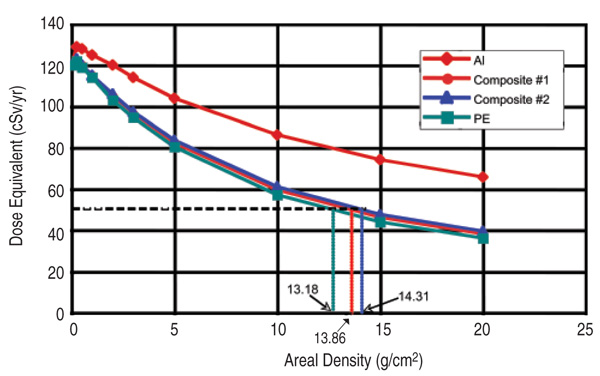
Figure 1 shows transport calculation
results for the two described composites.
Calculation results for aluminum
and PE are also included for
comparison. Results presented in Figure
1 are based on the assumption of
a solar-minimum condition when the
GCR flux is at a maximum. Similar results
were obtained when the 1989 solar
maximum environment was used.
These calculations indicate that over
thicknesses ranging from 1 g/cm2 to
20 g/cm2 the shielding effectiveness of
Composite 1 is only about 1% to 5%
less than that for pure PE. The entire
composite structure, including thermal
and ballistic protection, is only
2% to 8% less effective than pure PE
over the same thickness range. Terrestrial
and LEO requirements mandate
keeping the exposure below 50 cSv/
year for blood forming organs.1 Using
this requirement as an example, it can
be seen from Figure 1 that compared
to PE only a marginal increase in
composite areal density (13.86 g/cm2
for Composite 1 and 14.13 g/cm2 for
Composite 2 in comparison to 13.18
g/cm2 for pure PE) will be required
to achieve the same level of shielding
provided by PE. However, as will be illustrated later, this increase in areal
density compared to PE is offset by
gains in the composites multifunctional
properties.
Development of the
Composite Architecture
Composite 1: Structure
and Radiation Shielding
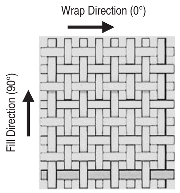
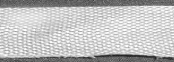
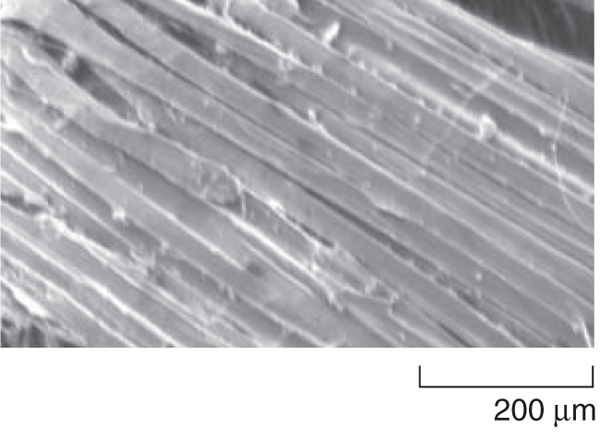
The material product form used to
fabricate the composite consisted of
a high-strength fabric that was plain
woven from UHMW PE Spectra 1000
fibers. Individual fibers were 30 µm in
diameter with ultimate tensile strength
(UTS) and modulus in the range of
3 GPa and 103 GPa, respectively.16 A
typical plain weave consists of fibers
laid in the 0º warp and 90º fill direction
as schematically shown in Figure 2a. A
single-ply UHMWPE fabric is shown
in Figure 2b. Several such plies were
hand laid using a thermoset resin typically
employed for aerospace applications.
The resin system was selected
based on its long pot life desirable for
hand lay-up operations and its reasonably
high glass transition temperature
of 90ºC. To enhance adhesion between
the PE fabric and resin, the fabric was
gas plasma treated prior to the composite
lay up. For the current application,
the fabric was oxidized during the plasma
treatment. Gas plasma treatment
promotes superior adhesion through
surface roughening and increasing the
surface area of the fiber, and by generating
oxygen-containing functional
groups on the fiber surface.17 After lay
up, the composite was autoclaved at
600 kPa for 24 hours during final curing.
The natural exotherm produced
by the resin system during curing was
monitored and kept below 90ºC. The
finished composite was in the form of
a plate with desired dimensions for either
radiation or mechanical testing. A
typical 30.5 cm3 × 15.2 cm3 × 1.27 cm3
Composite 1 plate is shown in Figure
2c. Composite 1 was used for characterization of mechanical and radiation
shielding properties.
Composite 2: Architecture with
Thermal and Ballistic Protection
Multifunctionality
A second composite sample, designated
Composite 2, was fabricated
to further enhance the multifunctional
nature of the composite by addressing
thermal management and ballistic impact
resistance properties. A thermal
protection system (TPS) is typically
employed to withstand the space environment
and extremely high heat
flux encountered during re-entry. For
example, the black high-temperature
reusable surface insulation (HRSI)
tiles typically seen on the belly of the
space shuttle are exposed to approximately
1,300ºC during re-entry.18 It is
anticipated that re-entry from a lunar
mission will expose the vehicle to even
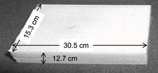
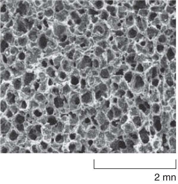
higher temperatures. A combination of
an open-cell carbon foam and plasma deposited
B4C coating on the exterior
surface of the carbon foam was used to
address these requirements (see Figure
3a). A coal-based carbon foam was selected
primarily because of its low density
(0.268 g/cm3), low thermal conductivity
(0.255 W/mK depending on the
cell structure), and ability to withstand
temperatures up to 3,000ºC in a nonoxidizing
atmosphere or with suitable
surface protection. Thermal conductivity
of the carbon foam is comparable to
that of the HRSI tiles used on the space
shuttle.
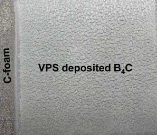
B4C was deposited on the surface of
the carbon foam via vacuum plasma
spraying (VPS). An as-deposited B4C
coating is shown in Figure 3b. The texture
of the B4C coating reflects the texture
of the carbon foam substrate surface.
The 1 mm thick coating was deposited
using a B4C powder feedstock
fed through an argon plasma with H2
assist gas. The VPS technique was used
for this application because it provides
a durable mechanical and metallurgical
bond between the carbon and B4C
without the use of low-temperature materials
or bonding agents. Durability is
essential for high-temperature applications
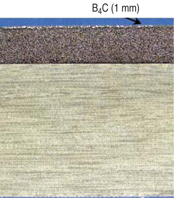
such as re-entry vehicles. In addition,
the VPS process has the ability to
rapidly produce an adherent deposit on
curved surfaces and for acreage applications.
A 1.25 cm thick carbon foam
brick with the B4C coating was bonded
to the PE composite using the matrix
epoxy. The complete architecture of
Composite 2 is shown in Figure 3c.
This composite was characterized for
radiation shielding effectiveness, hypervelocity
ballistic impact resistance,
and thermal exposure characteristics.
Table I.
Density of Hydrogen
Atoms in
Different Materials
|
| Material |
# Atoms/cm3 × 1022 |
| Hydrogen |
5.7 |
| Water |
6.7 |
| Polyethylene |
7.9 |
| Polystyrene |
4.7 |
| Polyimide |
2.2 |
| Polyamide |
3.0 |
|
Heavy Ion Exposure
of Composites
Since it is currently not feasible to
test the radiation-shielding effectiveness
of new materials in the free space
GCR environment, the only realistic
way to experimentally assess the shielding
effectiveness of these materials is
to expose them to heavy ion beams
at an accelerator facility. Availability
of beam time and appropriate beam
type for such experiments can be limited
since only two such facilities exist
worldwide: the NASA Space Radiation
Laboratory (NSRL) at the Brookhaven National Laboratory, and the Heavy
Ion Medical Accelerator (HIMAC) in
Chiba, Japan. An 800 MeV/u 28Si (incident
LET 45.96 keV/µm) beam, a
reasonably good GCR-proxy beam for
shielding effectiveness evaluation,11,12
was made available for exposure of the
composite samples at HIMAC. Exposures
were carried out with the assistance
of personnel at NSRL. During
the exposure several silicon detectors
were placed upstream and downstream
of the sample. Upstream detectors were
used to verify the monochromatic beam
source while the downstream detectors
were used to determine the charges of
the particles emitting from the sample
material. Further details related to detector
stacks, data acquisition, and
shielding analysis have been presented
elsewhere.11
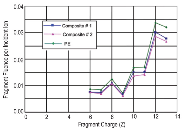
Figure 4 shows the absolute fragment
fluence per incident ion as a
function of fragment charge for the
composite samples as well as for PE.
Fragment fluence, one of the metrics
used for measuring radiation-shielding
effectiveness, is defined as the number
of particles with charge Z emerging
from the downstream side of the sample
within a 1 cm2 circle centered on the
beam axis. This metric is essentially a
measure of the capability of a material
to fragment heavy charged particles
into lighter charged particles. On this
basis, Figure 4 clearly illustrates that
both Composites 1 and 2 are capable of
fragmenting the incoming silicon beam
(Z = 14), and their performance is comparable
to that of the benchmark PE
material. It should be noted that fragments
with Z < 6 were not resolved by
the detectors and as such are not shown
in the figure.
It is customary for accelerator exposure
measurements not to estimate the
systematic uncertainties (which are
typically of the order of 2% to 5%) for
the sake of time and resource optimization.
As a result only values that are
relative to a benchmark material, PE in
this case, should be evaluated. Table II
lists some of these relative metrics to
evaluate the shielding effectiveness of
the two composites. In terms of surviving
fractions (or attenuation) of the primary
silicon beam, the composites are
a maximum of 7.2% inferior to PE. In
addition, the two composites are marginally
(3.44.2%) inferior to PE both
in terms of dose and dose-equivalent. It
is equally important to note from the
data that the measured shielding effectiveness
of the composite samples (areal
density = 4.4 g/cm2) are in agreement
with the transport calculation results
presented
in Figure 1. Hence, based on
both experimental measurements and
transport calculations it is reasonable to
conclude that the developed composites
will have shielding effectiveness comparable
to PE and definitely much superior
to currently used aluminum alloys.
Table II. Absolute and Relative (to PE) Values of Radiation Shielding Effectiveness Metrics
for the Composite Samples from the 800 MeV/u28Si Beam Exposure*
|
| |
Surviving Fraction
of the Primaries |
Absorbed Dose (nGy) |
AVG. Q After
(nSv) |
Dose Equivalent |
Target |
Abs. |
Rel. |
Abs. |
Rel. |
Target |
Abs. |
Rel. |
| C #1 |
0.675 |
1.060 |
57.6 |
1.034 |
12.64 |
727.9 |
1.037 |
| C #2 |
0.683 |
1.072 |
57.8 |
1.038 |
12.65 |
731.5 |
1.042 |
| PE |
0.637 |
1.000 |
55.7 |
1.000 |
12.61 |
702.0 |
1.000 |
All samples were approximately 4.4 gm/cm2 thick.; C #1 = Composite 1, C #2 = Composite 2.
|
Composite 1:
Characterization of
Mechanical Properties
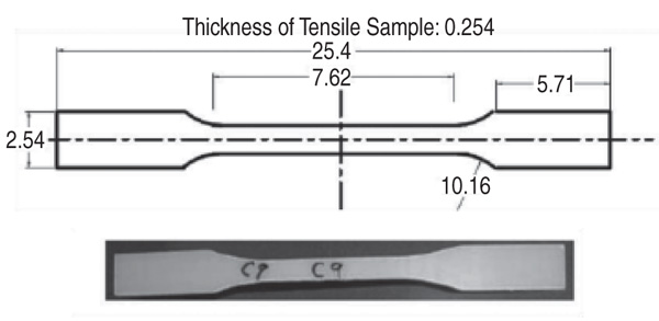
Panels of Composite 1 were machined
using a waterjet to obtain dogbone
tensile testing samples according
to ASTM D 638-03 specifications (see
Figure 5). During testing, titanium tabs
were used to reduce stress concentration
and to prevent grip damage at the
sample ends. Constant displacement
tensile testing was performed using a load cell of 100 kN. A total of seven
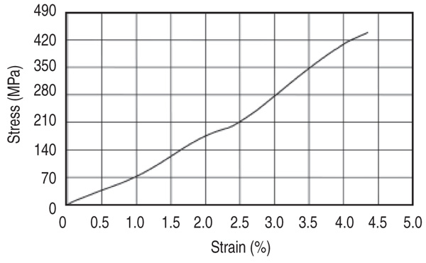
Composite 1 samples were tested. A
representative stress-strain curve for
Composite 1 is shown in Figure 6. Unlike
metallic systems, a typical yield
point is not obvious for such composites.
As expected, the epoxy matrix
failed first, and this is indicated by the
change in slope between 1.5% and
2.4% strain. Beyond this point the load
was completely transferred to the PE
fabric until failure occurred at about
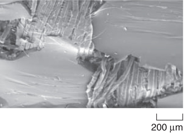
4.4% strain. Figure 6b shows the failure
of the epoxy matrix while the PE fiber
bundles appear to be bound and compact.
Even at final fracture of the composite
(see Figure 6c) there was hardly
any indication of fibrillation at the fractured
surface since the presence of epoxy
is clearly evident between the fiber
bundles. This desirable behavior of the
composite structure can be attributed to
superior surface adhesion between the
fabric and the epoxy matrix as a result
of the fabric surface treatment using
gas plasma.
The average measured UTS and elastic
modulus of Composite 1 along with
properties of aluminum alloys such as
Al 5052, Al 2219, and Al 2024 are listed19,20
in Table III. These alloys are typically
used for space applications such
as the International Space Station modules
and space shuttle fuselage. It is
evident that the PE fabric composite
has UTS and specific modulus values
comparable to the aluminum alloys.
However, their main advantage is highlighted
in the two density and UTS columns
within Table III. Composite 1 is
about 2.8 times lighter (lower density)
than the aluminum alloys, and consequently
its specific strength (strength/
weight ratio) is 2.5 to 4 times greater
than typical aerospace aluminum alloys.
The preliminary radiation shielding
and mechanical testing data presented
in this paper for Composite 1
clearly illustrate that the proposed composite deserves further attention as a viable
multifunctional material for replacing
traditional aluminum alloys.
Ballistic Properties of
Composites 1 and 2
For any composite architecture to be
considered for a crew vehicle application
its ballistic properties, for example,
micrometeoroid impact response, have
to be addressed. Terrestrially, the micrometeoroid
environment can be simulated
by impacting the test material
with soda lime glass bead projectiles
0.4 mm in diameter at velocities in the
range of 67 km/s. The experimental
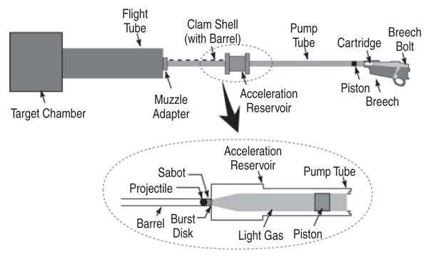
system used for such testing is a two stage
micro-light gas gun (MLGG) as
shown in Figure 7. In the first stage, an
explosion at the breach end moves a
piston forward, which compresses H2
gas behind a diaphragm. Once the diaphragm
is ruptured, the second stage
initiates where the compressed gas enters
the barrel and moves the projectile
at hyper velocities. The projectile finally enters the target chamber where it
impacts the target. The low molecular
weight of H2 provides the ultra-highvelocity
flows needed to achieve hyper
velocities.
The effectiveness of micrometeoroid
impact resistance was quantified
by measuring the crater diameter and
the damage diameter of the samples
after ballistic impact testing. The initial
impact of the projectile results in
a straight and narrow track, and its diameter
is defined as the crater diameter.
The subsequent shock wave generated
within the target material is absorbed
either through straining of the matrix or
by creating new surfaces. The new surfaces
are manifested as a damaged area
and can be quantified by a corresponding
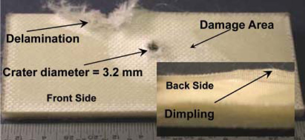
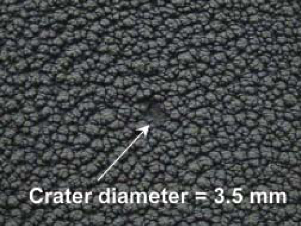
damage diameter. As can be seen
from Figure 8a, the projectile impact
created a 3.2 mm diameter crater on the
impact surface of Composite 1. In addition,
the extremely high strain rate was
manifested in the form of delamination
and dimpling on the back surface of the
composite. In comparison, the VPS-deposited
B4C coating only had a comparable
crater diameter with no associated
damage area (Figure 8b). There was no
indication of spalling or erosion on the
underlying carbon foam.
To obtain a better insight into the
significant improvement in ballistic
resistance of Composite 2, a numerical
modeling scheme was undertaken.
Relevant properties, such as density,
modulus of elasticity, shear modulus
and Poissons ratio, for both B4C and
carbon foam were obtained from the
literature.21 A finite element model
builder was used to mesh the B4C coating
with 162,500 elements and the glass
bead projectile with 2,275 elements. To
match the experimental conditions, the
imposed projectile impact velocity was
6 km/s. Based on the materials properties,
failure strain (FS) of 0.12 and 0.01
were used for the B4C and projectile,
respectively. As part of the modeling
scheme, a failure strain erosion criterion
was used such that the elements
within the B4C coating and glass bead
projectile were eroded once the plastic
strain within those elements exceed
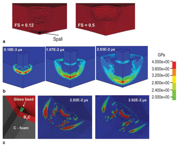
0.12 and 0.01, respectively. Figure 9a
shows an example of the effect of hypervelocity
ballistic impact as a function
of failure strain. For FS = 0.12, the damage is more localized, and plastic
strain is sufficient to cause erosion
(spalling) of elements at the distal side
of the B4C coating. This is exactly what
was observed for Composite 2 (Figure
8b). If, for example, B4C was replaced
by a material with FS = 0.5, no spalling
would be observed at the distal
side. However, the damage would no
longer be localized, and would instead
be manifested as bulking or volume
change. The FS value for PE is much
higher than 0.5, and therefore the more
widespread damage observed for Composite
1 (Figure 8a) is not surprising.
The projectile was completely eroded
at the very early stages of impact. The
model predicted that on impact a compressive
stress wave of 4 GPa would
be generated in the composite ahead
of the projectile. Figure 9b shows the
propagation of this compressive wave
as a function of time. The effect of this compressive wave on the underlying
carbon foam needs further analysis.
The impact response of the two component
system consisting of the
B4C deposit and the underlying carbon
foam was simulated to investigate
whether the compressive stress wave
would traverse through the carbon
foam. Figure 9c shows the mesh profile
at the interface of the two component
system. The longitudinal and transverse
wave velocity, VE and VG respectively,
in a medium can be expressed as
where K1 is bulk modulus, G is the
shear modulus, and o is the density.
Since both G and K for carbon foam
are almost three orders of magnitude
less than the values of B4C, VE, and
VG in carbon foam are almost 18 times
less than in B4C. The model predicts
that the compressive wave is not transmitted
through the carbon foam but is
instead reflected back into the B4C top
layer. This reflection is shown in Figure
9c at time steps 2.92 × 10² µs and
3.92 × 10² μs. This reflected wave
potentially caused spalling on the distal
side of the B4C layer. Previous experimental
and modeling studies conducted
on multilayer composites have
also shown that a low modulus material
such as carbon foam is preferable for
prevention or minimization of longitudinal
wave transmission.22 The experimental
and modeling results presented
here demonstrate that the proposed
composite architecture is capable of
protecting the underlying PE structural
layer from hypervelocity micrometeoroid
impact.
Table III. Measured Mechanical Properties of Composite 1 in Comparison to Some
Traditional Al Alloys used in Spacecraft Structures
|
| Material Type |
UTS (MPa) |
Density (kg/m3) |
Specific UTS (N-m/kg) |
Specific Modulus (N-m/kg) |
| Composite 1 |
447 |
980 |
45 x 105 |
21.5 |
| Al 2024/T81 |
481 |
2,768 |
1.7 x 10⁵ |
25.5 |
| Al 2219/T81 |
455 |
2,851 |
1.5 x 10⁵ |
26.8 |
| Al 5052/H38 |
290 |
2,680 |
1.08 x 10⁵ |
25.2 |
|
Thermal
Characteristics
of Composite 2
A preliminary assessment of the
thermal characteristics of Composite 2
was performed to determine the ability
of B4C coating and carbon foam to protect
the underlying structural PE composite
when subjected to the high temperatures
experienced during spacecraft
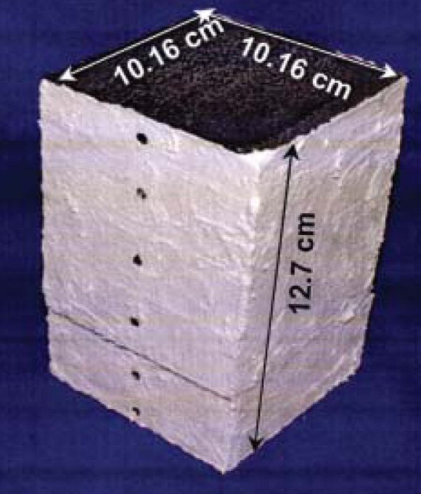
re-entry in Earths atmosphere. Several
pieces of carbon foam were adhered
together using a high-temperature
carbon-based adhesive to fabricate a
10.1 cm3 × 10.1 cm3 × 12.7 cm3 test
block (Figure 10a). The test block
was dried at room temperature for 48
hours, then cured at 130ºC for 4 hours
and 260ºC for 2 hours to remove adhesive
volatiles. Sample thickness was
12.7 cm to closely duplicate the thickness
of the HRSI space shuttle tiles.
The top surface of the carbon foam
was coated with a 1 mm thick B4C
layer using the VPS technique as described earlier. The sides of the carbon
foam were coated with an Al2O3 paste
to prevent excessive oxidation during
the high-temperature test. Six thermocouples
located along the centerline of
the test block were used to monitor the
temperature profile through the thickness.
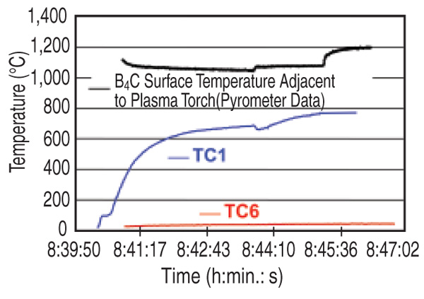
During testing the B4C face of the
test block was exposed to a high-temperature
plasma for a duration of 7
minutes to produce the temperature
profile shown in Figure 10b. A maximum
surface temperature of 1,200ºC
was measured for the B4C coating using
a two-color pyrometer. However, it
should be emphasized that the pyrometer
was placed at an approximate angle
of 45º to the B4C face, and it was aimed
a few centimeters away from the point
of plasma impingement. Therefore, the
temperature at the point of impingement
was greater than 1,200ºC. The
distance
between the plasma and the
test block was reduced twice to obtain
higher test temperatures. Visible light
glow signifying extreme heating at
the point of plasma impingement was
observed only when the distance was
reduced to 3 cm. The test duration of
7 minutes was reasonably close to the
re-entry time of 812 minutes recorded
during the Apollo lunar missions.23
Two thermocouple profiles (TC1 and
TC6) are shown in Figure 10b. TC1
was placed 6.7 mm below the B4C
and the carbon foam interface while
TC6 was positioned 12.1 cm below the
coating interface of the 12.7 cm thick
test block. TC1 recorded a maximum
temperature of about 800ºC during the
test. This indicates that the B4C coating
provided significant thermal protection
by dropping the temperature by more
than 400ºC over a thickness of 6.7 mm.
More importantly, the temperature profile
recorded by TC6 indicates a maximum
temperature of 39ºC for the duration
of the test. Therefore, a structural
PE composite placed below the 12.7 cm
thick thermal protection system would
be adequately protected. The thermal
protection capability presented here is
preliminary. Further refinement of the
surface temperature measurement system
is required to accurately estimate
the high-temperature capabilities of the
proposed system. However, this preliminary
testing demonstrates a path
toward development of a complementary
thermal protection system without
significant sacrifice of the radiation
shielding effectiveness.
CONCLUSIONS
Simulation results indicated that
over thicknesses ranging from 1 g/cm2
to 20 g/cm2, Composite 1 was only
about 1% to 5% less effective than pure
PE, while the entire composite structure,
including thermal and ballistic
protection, was only 2% to 8% less effective
compared to pure PE. However,
transport code analysis indicated that
the composites were much superior
to traditional aluminum aerospace alloys.
These predictions were validated
by subsequent sample construction
and 800 MeV/µ 28Si beam testing. The
measured mechanical, ballistic, and
thermal properties indicate that a multifunctional
composite approach can
significantly compensate for the marginal
increase in areal density required
for the composites to be comparable to
pure PE in terms of radiation shielding
effectiveness. Tensile strength measurement
demonstrated that the developed
composites have specific strength
2.5 to 4 times greater than typical aluminum
aerospace alloys. Numerical
evaluation and experimental validation
demonstrated that selection of an
open cell carbon foam material with
a VPS deposited B4C coating can be
instrumental in providing protection
from micro-meteoroid impact and re-entry
temperatures to an underlying PE
structural composite.
During ballistic testing, the B4C
coating was responsible for complete
erosion of the projectile almost on
impact. Extremely low bulk and shear
modulus of the carbon foam prevented
transmission of the compressive stress
wave generated during impact, thereby
protecting the underlying structural
composite material. Also of note is
the versatility of the VPS technique in
depositing a well adhered B4C coating
even on an irregular surface such
as the open cell C foam, circumventing
the problems typically associated
with depositing coatings on curved and
uneven surfaces for high-temperature
use. Thermal testing indicated that on
exposing the B4C layer to temperatures
1,200ºC and above, the maximum temperature
recorded at the bottom of the
12.7 cm thick carbon foam sample did
not exceed 40ºC. This thermal capability
is comparable to that of the high temperature
ceramic tiles that are currently
used on the space shuttle.
It should be noted that expected reentry
temperatures from a lunar mission
will be higher, and hence much
more elaborate and accurate characterization
of thermal management
schemes are mandated. Nevertheless,
this paper has demonstrated the validity
and importance of a multifunctional
composite architecture that could potentially
circumvent the problem of
paying a penalty in additional weight
to implement passive radiation shielding.
Such a multifunctional composite
holds the key for safe long duration
missions beyond LEO. As a first step,
the developed composites were selected
by NASAs Materials International
Space Station Experiment program
for further evaluation. As part of this
evaluation these samples have recently
been attached to the aft side of the International
Space Station and will be
exposed to the LEO environment for
approximately 6 months.
ACKNOWLEDGEMENTS
The authors are grateful to the NASA
Small Business Innovative Research
program for funding this effort. The
experimental nuclear physics group
at Brookhaven National Laboratory,
New York, is acknowledged for support
and expertise during exposure of the
samples to heavy ion beams and data
reduction. The authors are also grateful
to Dr. Sheila Thibeault of NASAs
Langley Research Center for technical
discussions and encouragement during
the course of the project. The authors
wish to express their gratitude to Ms.
Ernestine Cothran of BAE Systems for
her patience and dedication through
resolving administrative issues toward
the project.
REFERENCES
1. Guidance on Radiation Received in Space
Activities, National Council on Radiation Protection
and Measurements Report No. 98 (1989).
2. G.D. Badhwar and P. ONeill, Adv. Space Res., 17
(2) (1996), pp. 717.
3. J.W. Wilson, Health Phys., 79 (5) (2000), p. 470.
4. M.A. Shea and D.F. Smart, Solar Phys., 127 (June
1990), pp. 297320.
5. T.A. Parnell, J.W. Watts, and T.W. Armstrong,
Radiation Effects and Protection for Moon and Mars
Mission, Proceedings of the Sixth International
Conference and Exposition on Engineering,
Construction, and Operations in Space, Space 98
(Reston, VA: American Society of Civil Engineers,
1998), pp. 232234.
6. H. Smith, editor, 1990 Recommendations of the
International Commission on Radiological Protection,
Annals of the ICRP, vol. 21/1-3 (New York: Pergamon
Press, 1991).
7. The Relative Biological Effectiveness of Radiations
of Different Quality, National Council on Radiation
Protection and Measurements Report No. 104 (1990).
8. J.W. Wilson et al., NASA Technical Paper 3682
(Hampton, VA: Langley Research Center, December
1997).
9. J.E. Turner, Atoms, Radiation, and Radiation
Protection, 2nd edition (New York: Wiley-Interscience
Publishers, 1995), pp. 160161, 350351.
10. F.A. Cucinotta et al., Adv. Space Res., 17 (2)
(1996), pp. 7786.
11. S. Guetersloh et al., Nucl. Instr. and Meth. in Phys.
Res. B., 252 (2006), pp. 319332.
12. R.K. Kaul, A.F. Barghouty, and H.M. Dache,
Radiation Transport Properties of PolyethyleneFiber
Composites, Proceedings of the Conference on
Microgravity Transport Processes in Fluid, Thermal,
Biological, and Materials Sciences (New York: Annals
of the New York Academy of Sciences, 2004), pp.
138149.
13. J. Miller et al., Rad Res., 159 (2003), pp. 381390.
14. J.W. Wilson et al., NASA Report #1257 (Washington,
D.C.: NASA, 1994).
15. P.M. ONeil, Adv. Space Res., 37 (2006), pp. 1727
1733.
16. F.C. Campbell, Manufacturing Technology for
Aerospace Structural Materials, 1st edition (Amsterdam,
The Netherlands: Elsevier Ltd., 2006).
17. D.M. Choi et al., Polymer, 38 (25) (1997), pp.
62436249.
18. Reusable Launch Vehicle Technology Development
and Test Program, report submitted by the Committee
on Reusable Launch Vehicle Technology and Test
Program (Washington, D.C.: National Academy Press,
1995).
19. ASM Materials Handbook, Volume 20 (Materials
Park, OH: ASM International, 2001).
20. Aluminum Standards and Data (Arlington, VA: The
Aluminum Association Publication, 2006), pp. 2-22-3.
21. G. Johnson and T. Holmquist, J. Appl. Phys., 85 (12)
(1999), pp. 80608073.
22. A. Tasdemirci and W. Hall, J. Comp Mat., 39 (11)
(2005), pp. 9811005.
23. J.E. Pavlosky and L.G. St. Leger, NASA Technical
Note # TN D-7564 (Washington, D.C.: NASA, January
1974).
S. Sen, principal scientist for the NASA Program,
is with BAE Systems, NASA Marshall Space Flight
Center/EM 30, Building 4464, Room 111A, Huntsville,
AL 35812, USA. E. Schofield, materials engineer,
and J.S. ODell, project engineering manager, are
with Plasma Processes Inc., Huntsville, Alabama.
L. Deka, materials engineer, and S. Pillay, assistant
professor, are with the Department of Material
Science & Engineering, University of Alabama at
Birmingham. Dr. Sen can be reached at (256) 544-
8264; fax (256) 544-6660; e-mail Subhayu.Sen-1@nasa.gov.
|
 Presenting a Web-Enhanced