Presenting a Web-Enhanced Presenting a Web-Enhanced Article from JOM |
LATEST ISSUE |
|||
TMS QUICK LINKS: |
• TECHNICAL QUESTIONS • NEWS ROOM • ABOUT TMS • SITE MAP • CONTACT US |
JOM QUICK LINKS: |
• COVER GALLERY • CLASSIFIED ADS • SUBJECT INDEXES • AUTHORS KIT • ADVERTISE |
|
| Multi-scale Modeling of Metal Forming | Vol. 63, No.11 pp. 24-32 |
Approach to Modeling Aluminum
Deformation
P.E. Krajewski, L.G. Hector, Jr., Y. Qi, R.K. Mishra, A.K. Sachdev, A.F. Bower, and W.A. Curtin
Questions? Contact jom@tms.org. |

|
A multi-scale, computational design approach for aluminum sheet alloys, which includes key inputs from the electronic, atomistic, microstructural, and continuum length scales, is reviewed within the context of room and elevated temperature forming. Specific examples, which are aimed at improving aluminum sheet materials for automobile components, include prediction of flow curves from tensile testing, forming limit diagrams, and component forming.
The range and complexity of materials now used in metal forming processes is continually expanding the gap between simulation and the availability of accurate constitutive models and failure criteria to represent their behavior. In the auto industry, there is a need to utilize lightweight metals such as advanced high strength steels, aluminum, and magnesium to improve vehicle fuel economy and performance. Due to their limited formability, these materials often require novel forming processes which utilize load cases, temperatures, and strain rates that are not common in automotive manufacturing. The constitutive equations which govern the forming and performance of these materials are typically developed through extensive mechanical testing and characterization which is time consuming and expensive. Moreover, material model development is largely dependent on continuum scale phenomena and ignores the rich multiscale physical and chemical phenomena that are responsible for the macroscale plastic deformation response of a polycrystalline metal. The substantial complexity of these phenomena, which occur through the evolution of microstructure and texture in response to strain, presents formidable challenges to theoretical model development of plastic deformation. General Motors Company, with
Brown University and other collaborators,
is engaged in an "Atoms to
Autos" research program to develop
computational techniques to speed
the development of lightweight sheet
materials and their deformation processes
to enable increased use of these
materials in the automotive industry.
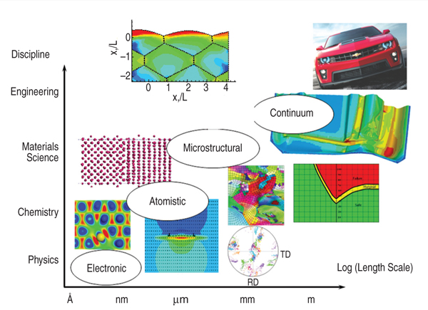
The framework that we have used is
based upon a multi-scale modeling approach,
shown schematically in Figure
1, which requires a deeper understanding
of operative metallurgical phenomena during deformation. The inference
from Figure 1 is that the process of
multi-scale modeling of material constants
requires inputs from different
length scales, the smallest of which is
the length scale over which electronic
structure is accounted for (up to ~103
atoms), and the largest being the continuum
which is the domain of engineering.
In between lie the atomistic (≤104
atoms) and microstructural (grain size)
length scales. Our multi-scale modeling
approach employs a combination
of modeling techniques including
quantum mechanical (QM) description
of electronic structure via density functional
theory (DFT), molecular dynamics
(MD), crystal mechanics/plasticity,
and continuum finite element modeling
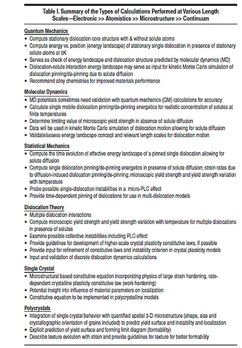
(FEM). Details about each of these calculations
and their outputs are summarized
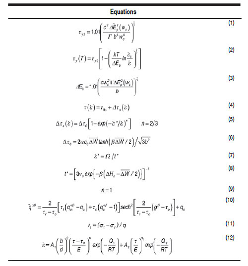
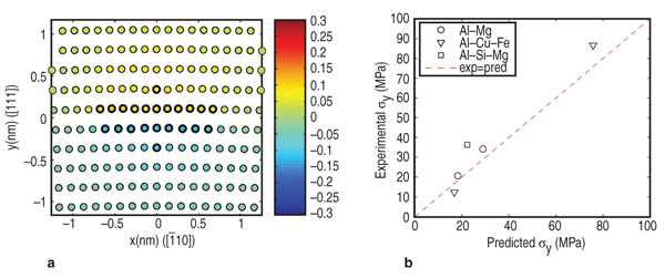
in Table I. Our approach is tailored to the unique aspects of a given material, with the thrust being an understanding of the key physical and chemical mechanisms that govern plastic deformation behavior. The desired outcome is the ability to develop inputs to FEM simulations through computational approaches with the use of embedded or informed constitutive equations and failure criteria rather than experimental characterization and data-fitting. This approach can also provide input data to higher length scale models when experimental data is not available or is difficult to generate and thus reduce the number of approximations needed for numerical simulations. The ultimate goal of this multi-scale approach is to develop new materials with improved formability and end-use performance, and to improve upon the finite element prediction of their forming and performance with informed constitutive equations. In this paper, we highlight our recent successes in multi-scale modeling of Al-Mg alloys. These alloys have already seen extensive use in automobiles in the form of AA5182, AA5754, and AA5083 and they offer an excellent combination of formability and strength. We have selected five different types of calculations to demonstrate the approach. These include predicting the effect of solutes on yield strength, solutes on strain rate sensitivity in tensile behavior, hardening and microstructure effects on forming limit diagrams, microalloying on grain boundary sliding, and various deformation mechanisms active during high temperature forming. For clarity of presentation, these examples are discussed in two separate sections: one applicable to room temperature forming, such as conventional stamping, and the second for elevated temperature forming processes, such as quick plastic forming (QPF). The individual approaches and calculations are summarized, and the opportunities for using these calculations in material design are highlighted Conventional stamping at room temperature is the primary method for making automotive body panels, which presents a challenge for aluminum sheet materials due to their lower formability compared to steel. A large portion of our multi-scale modeling initiative focuses on calculations to improve the development of new aluminum materials for room-temperature stamping. The challenge is to develop materials with formability comparable to cold rolled steel, without compromising strength or other performance attributes such as corrosion, paintability, etc. The strength of Al-Mg alloys is mainly controlled by solute strengthening. The addition of magnesium solute up to 5 wt.% has been shown to increase strength without reducing ductility.1 However, one of the key drawbacks to many Al-Mg alloys is that they exhibit a negative strain rate exponent sensitivity (nSRS) or m, and dynamic strain aging (DSA) at room temperature. Associated with the nSRS is reduced ductility, which compromises formability and can produce irregularities on the surface of formed parts which limits their use to non-exposed surface applications.2 Electronic Structure Central to theoretical models of solute strengthening and diffusion are accurate dislocation core structures. Since dislocation core structure cannot be predicted by classical continuum elasticity dislocation models, we combined DFT3 with the Lattice Green's function (LGF) technique4 to predict the core structure of an aluminum edge dislocation. The DFT formalism, which is now one of the important computational materials science tools,5 provides energies, while the LGF technique correctly couples dislocation core structure to the long range elastic field of the dislocation. We find that an aluminum edge dislocation, for example, dissociates into two Shockley partials separated by ~10.8 Å.6 This very narrow core spreading presents significant challenges to experimental investigations of dislocation structure in aluminum. With the DFT-predicted core structure, we focused on solute strengthening. We first computed solute/dislocation interaction energies for a range of relevant solute additions with DFT for solutes in the immediate core (i.e. in the stacking fault region) of an aluminum edge dislocation (a similar procedure applies for the screw core). We limit our focus here to magnesium solutes. Figure 2a shows contours of U (xi, yj), which is the solute/dislocation interaction energy as a function of position (xi, yj) in the DFT-predicted core. To accomplish this, we placed solutes at the sites denoted by darkened circles. Favorable binding energies are denoted by negative values (energies are in eV), so that magnesium prefers to reside on the tension side of the core: this is consistent with the fact that magnesium solute is larger than the Al. The interaction energies were then
used in a parameter-free analytic theory
that enables prediction of 0K shear
flow stress, τy0, for binary Al-Mg alloys
as a function of temperature and strain
rate.6 The theory considers the motion
of a dislocation through a random distribution
of solutes in the host matrix.
The derivation is beyond the scope of
this article, and so we simply quote
the major results (Equation 1), where
c is solute concentration, b is Burgers
vector, Atomistic Models of DSA and nSRS incorporate
a critical resolved shear stress
(or resistance to dislocation glide) of
the form Equation 4, where τ0s
is due to other strengthening mechanisms
(strain hardening, and SRS associated
with the activation of overcoming
short-range obstacles in the absence
of nSRS). The standard form for additive
strengthening (or resolved shear
stress to move a dislocation), Δτs ( From our model, we are able to
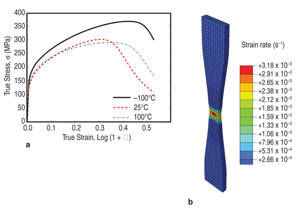
predict expressions for Δτ0, The cross-core diffusion mechanism was validated using our multi-scale modeling approach. This involved two atomistic techniques: molecular statics (which uses semi-empirical potentials rather than quantum mechanics) to predict magnesium energies in the aluminum core, and kinetic Monte Carlo (kMC) to validate the effect of magnesium cross core diffusion. In kMC, magnesium atoms are moved toward their equilibrium (i.e., energetically preferred) sites at a rate corresponding to their local diffusion rate at a specified temperature. Each atom movement is based upon a computed probability for that movement. We have developed a full rate theory for plastic flow in the presence of DSA incorporating the theory outlined above. We find that the cross-core process, which occurs on all dislocations, both mobiles and forests, has an important influence on the forest strengthening contribution to the alloy stress-strain response. The full rate theory, with inclusion of forest hardening and DSA effects on the forest hardening, is described in Reference 11. This development enables us to implement the atomistically informed constitutive law into a robust continuum-level model such as the commercial code ABAQUS.12 An example of the predictive capability of this overall model is shown in Figure 3. The predicted stress-strain curves for a standard tensile specimen of AA5083 shown as a function of temperature. The model demonstrates the reduced ductility at 25°C where this material exhibits nSRS. Microstructural Effects In the atomically informed analytical model approach discussed above, we have considered the solute dislocation interaction and the dynamics of mobile and forest dislocation interactions with solutes, neglecting the dislocation and dislocation interactions as they occur during hardening. In general, the accuracy of any constitutive model depends on the theory that it is based on. A polycrystal model can be derived from single crystal deformation models to include anisotropic properties of single crystals, slip and/or twinning mechanisms, lattice rotation, and microstructural attributes such as grain size, grain shape, texture etc. Currently, finite element simulation codes rely on single crystal constitutive laws calibrated against polycrystalline data to reflect the complexity in the microstructure, hardening mechanisms etc., through approximations and fitting parameters. The challenge becomes the ability to establish a realistic, physically-based relation between the single crystal and polycrystalline models which therefore creates improved constitutive models. Many different approaches have been published in the literature to account for dislocation-dislocation interactions that include self and latent hardening effects in single crystals and polycrystals. Examination of the models and experimental data shows that serious deficiencies remain in accounting for hardening behavior even in single crystal aluminum. One such area is the way latent hardening is accounted for in constitutive models. Many different amounts and rates of hardening of different slip systems have not been accurately incorporated to predict the crossover in hardening curves along different crystallographic directions in face-centered cubic (f.c.c.) crystals for example.13 The measured latent hardening coefficients (LHC) in aluminum have values between 1 and 4, contrary to the typical assumptions available in the literature (0~1.4).14–16 This becomes important in simulating lattice rotation and texture evolution from a "finite element per grain" approach,17 which incorporates single crystal constitutive law and experimentally measured grain morphology and grain orientation information into polycrystal plasticity simulation to assess formability and forming limit curves. If single crystal constitutive equations do not include hardening in an accurate manner, the texture evolution and grain rotation, both of which are important in forming operations involving complex strain paths, are either underpredicted or overpredicted by polycrystal plasticity models. Lacking the development of a fully
atomistically informed model, we have
taken the approach to deal with the inadequacies
at their level and creating
the formalism in a way that can include
any advanced hardening law into this
model when it is developed and validated.
One example of this approach
is the way we have addressed the deficiency
in the implementation of latent
hardening in a fundamental manner.
Our approach in this case involves four
main steps. First, effects such as latent
hardening or thermally activated/athermal
hardening are modeled and tested
for self consistency in controlled single
crystal samples. Instead of fixed values
for latent hardening coefficients,
an evolution law to correlate the latent
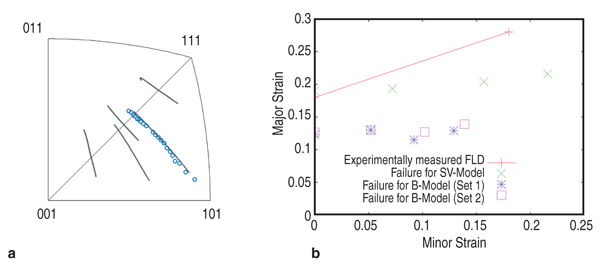
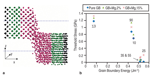
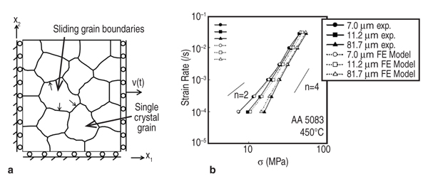
hardening coefficient Secondly, the predictions of these models are validated against independent experiments. As shown in Figure 4, this law is not only capable of predicting the overshoot tendency in lattice rotation for FCC materials, but also reproduces the experimental values of lattice rotation in an aluminum single crystal where such data is available. Thirdly, these laws are implemented into FEM codes through user material subroutines for bulk simulations via an embedded representative volume element (RVE) approach whose predictions can be compared with forming data from real materials. Such models successfully predict localization in polycrystals due to inhomogeneous deformation accompanying texture evolution. Lastly, by taking the experimental electron backscatter diffraction data as the input for a polycrystalline AA5754 sample, and incorporating any hardening law (such as the ones described above or the ones available in the literature), the forming limit diagram (FLD) for AA5754 sheets has been successfully computed and compared. The superior agreement between the computed FLD following this approach and experimental data shown in Figure 4b highlights how the microstructure-based model with physical mechanisms incorporated in the constitutive relations can discern the relative advantages and disadvantages of different constitutive approaches in modeling formability. In Figure 4b, (reproduced from Reference 20) the inadequacy of the Bassani–Wu law over the Saimoto–van Houte hardening law to predict FLD in AA5754 alloys is obvious although for simple strain path simulations such as tensile loading, such differences are not apparent. Evolution of inhomogeneous deformation at large strains is inherently included in such an approach for the simulation of FLDs, improving upon approximations such as the M-K analysis used in the continuum level models. Zhang et al.21 have shown that in single crystal aluminum, the value of strain to localization is highly sensitive to latent hardening behavior, underscoring the need for accurate hardening laws to be used in any FLD simulation. Material Design Opportunities and Challenges The results above show that it is possible to use microstructure-based models informed by constitutive laws derived using physics of solute-dislocation and dislocation-dislocation interactions to compute forming behavior. This approach, through "reverse engineering," also enables designing materials for improved formability by manipulating alloy chemistry at the atomic level and microstructure at the design at grain level. If the strength of Al-Mg alloys can be improved by either optimizing the magnesium content and/or the addition of other solutes, then the need for agehardening treatments could be reduced or even eliminated, stress corrosion cracking concerns could be greatly minimized, and improved weldability could be realized. We have investigated other solutes in aluminum alloys besides magnesium, namely silicon, and copper solutes among others to explore this aspect. The use of DFT allows, in principle, for the introduction of any element from the periodic table. Compared to magnesium, silicon, and copper atoms are smaller than aluminum atoms and hence these solutes will prefer to migrate to sites on the compression side of the dislocation core. The yield stress values in Figure 2b show that the predicted values for Al-Si and Al-Cu deviate from experiment. The difference between theory and experiment for these alloys is believed to be due to the presence of ppm levels of iron in the nominally binary experimental alloys.22 Other design variables such as solute concentration, forming temperature, and starting microstructure can similarly be explored and optimized using the above approach as these are inputs to the model and their influence on specific parameters in the constitutive relations are exactly known, unlike in phenomenological models where any parameter from the curve fitting procedure cannot be directly correlated with any microstructural or physical attribute of the material. The future for improving materials and processes rests on creating a polycrystal model informed by theory at lower length scales and accurately accounting for the mechanisms and microstructural details. The limited formability of aluminum has led to development of alternative forming processes to enable complex parts to be manufactured.23 Many of these processes, such as superplastic forming (SPF) and quick plastic forming (QPF), use elevated temperatures to improve formability. These processes require aluminum materials with fine (<10 μm) grain sizes to enable grain boundary sliding and give a positive strain rate sensitivity. As a result, these materials are often more expensive than commercial-grade materials. The focus of the present multi-scale research is to develop materials which can give improved elevated temperature performance (for example, biaxial dome height) and that can be processed in a cost effective manner. Modeling of Grain Boundary Sliding Grain boundary sliding (GBS) is a dominant deformation mechanism during elevated temperature forming of aluminum. The grain size, composition, and grain boundary orientation distribution play particularly important roles in determining flow stress and strain rate sensitivity. GBS of two grains under an external shear stress can be modeled by non-equilibrium molecular-dynamics (NEMD) (see Figure 5a).24 For pure aluminum, we found GBS velocity is linear function of the applied shear stress, as shown in Equation 11, where &sigmaa;C is the threshold stress, below which no sliding occurs and η is the grain boundary viscosity. The threshold stress decreases with increasing grain boundary energy for various grain boundaries we tested (Figure 5b). When the applied shear stress is too high, sliding accelerates with a premelting zone at the grain boundary.24 The influences of vacancies25 and solute atoms on GBS can be simulated by decorating the GB structure under different misorientation conditions with these defects. Microstructure-based Model for Elevated Temperature Deformation A microstructure-based model to
predict the elevated temperature flow
stress in polycrystalline aluminum as a
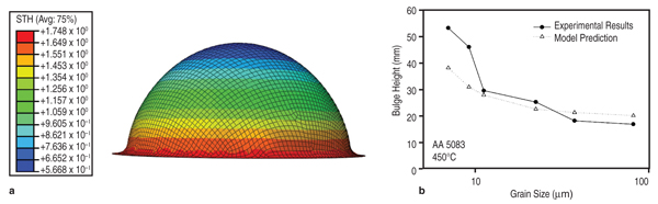
function of grain size, T, and The predicted variation of flow stress with strain rate for AA5083 with several different grain sizes is compared with experimental measurements in Figure 6b. The model predicts behavior that is in good agreement with our experiments: at strain rates above 10–3 s–1, the dominant deformation mechanism is solute drag creep, and consequently the stress exponent n approaches 4. At low strain rate, grain boundary sliding provides the dominant contribution to the total strain, so the stress exponent drops to n–2. The flow stresses predicted by this model can be fit by phenomenological constitutive equations for Al-Mg alloys that accounts for two-independent creep mechanisms,28,29 as shown in Equation 12, where b is the Burgers vector, d is the grain size, τ is applied stress, τo is the threshold stress for grain boundary sliding, Q is the activation energy, n is the stress exponent, T is the temperature, R is the gas constant, and E is the temperature compensated modulus. The subscript 1 refers to constants associated with grain boundary sliding, while subscript 2 refers to constants associated with dislocation creep. This constitutive equation is then used in finite element simulations of manufacturing processes of interest, for example, the dome height reached by a specimen in a simple, biaxial gas pressure dome forming experiment.30 Figure 7 compares the measured and predicted dome heights for materials with several grain sizes. The model predicts behavior that is in excellent agreement with experiments, with a small discrepancy for the material with grain sizes below 10 μm. The method has also been shown to successfully predict the location and extent of thinning during forming of a more complex three-dimensional closure component.31 Material Design Opportunities and Challenges One key opportunity for elevated temperature material design is to enhance GBS in relatively coarse grains. Previous research has determined that optimum forming occurs when GBS and dislocation creep contribute equally to deformation. Using the microstructure- based model, we have studied the effect of varying the threshold stress for GBS (τo)32 and grain boundary misorientation induced heterogeneity33 on elevated temperature flow. The results showed that the critical strain rate at which the deformation mechanism transitions from GBS to dislocation creep increases with the fraction of free sliding boundaries, thus suggesting improved forming. We have performed simulations using the NEMD model to explore how magnesium and silicon additions affects τo.34 As shown in Figure 5b, magnesium solutes increased τo of all grain boundaries because they formed immobile clusters with surrounding aluminum atoms due to the negative heat of formation of magnesium and aluminum. However, silicon solute atoms decreased (by approximately a factor of two) the sliding threshold in lowenergy grain boundaries by weakening aluminum bonds, increasing the mobility of the surrounding aluminum atoms, and consequently enhancing grain boundary diffusivity. To demonstrate the potential impact of modifying the grain boundary composition, we used the microstructure-based model for elevated temperature flow and assumed that adding silicon decreased the percentage of non-sliding boundaries from 43% to 23%. If we applied a stress of 10 MPa to the system, the resulting strain rate increased from 1.2×10⁻³ to 2.2×10⁻³s–1, which translates to faster cycle times and lower cost forming. The results above show that it is possible to use a microstructure-based model to compute parameters needed in finite element forming simulations of elevated temperature forming. The model provides the framework for a multi-scale computational approach so that we can design materials for improved formability and rapidly evaluate them in a forming operation. Ideally, values for the key parameters in the model should be determined from atomic scale models, but at present, atomic-scale models do not provide a fully quantitative description of elevated temperature flow behavior. For example, recent atomistic models which account in detail for the behavior of solutes in the dislocation core35 predict that the solute drag exponent n=3, different from experimentally determined n=4. The discrepancy is likely to be a consequence of over-simplifying the behavior of dislocations in the models, in which neglect climb, and assume all dislocations move at their steady-state velocity. Similarly, MD simulations predict a large τo for GBS and very high sliding velocities when τo is exceeded, compared to the macroscopic flow stresses observed experimentally during elevated temperature forming. MD simulations are likely to correctly predict the qualitative influence of GB structure on τo but quantitative predictions will require simulations over time-scales that greatly exceed the capability of current MD simulations. Obtaining quantitative predictions of grain boundary diffusivity from atomic scale computations poses similar challenges. The complexity of grain boundary structure also hinders generalizing and passing information from MD simulations to microstructure based FEM simulations. For example, microstructural information about grain boundary typically only contains mis-orientation angle, however grain boundary structures have five degrees of freedom. The grain boundary structures for alloys may even require new theories that treat the grain boundary as a separated phase, whose properties are orientation, atomic disordering, and chemistry dependent.36 Even at the molecular level, describing atomic interactions by accurate alloy atomic potentials still remains a great challenge. Due to the limitation of empirical potentials (availability, transferability, and accuracy), a general strategy for evaluating the influence of arbitrary solute atoms on GBS (or other deformation mechanism) should be using MD simulations with empirical potentials to identify critical atomic scale parameters that control GBS resistance. Then, more accurate quantum mechanics computations (such as DFT) can be used to identify solutes with the relevant properties. For example, the connection between heat of formation and bonding strength to τo indicates that the heat of formation can be used as a guide for grain boundary engineering. Heat of formation can be easily computed from more accurate DFT calculations37–39 or measured from experiments.40 In view of the difficulties in quantifying creep mechanisms at the atomic scale, at present parameters in our microstructure based model must be determined primarily from experiments. The parameters can be determined by measuring the flow stress of an aluminum alloy as a function of strain rate, for a single grain size. Further work will be required to develop accurate quantitative predictions of creep mechanisms at the atomic scale, before a fully predictive model of the effects of material composition on elevated temperature formability will be possible. Although, the microstructure level model continues to rely on some experimental calibration, it demonstrates that incorporating grain boundary structures, orientations, energies, defects (such as vacancy and solute atoms) dependence of the key GBS parameters (τo and η) into the microstructure based FEM forming modeling could ultimately lead to microstructure optimization and novel material processing design. The multi-scale methodology described in this paper provides an approach for obtaining accurate constitutive laws based on physical phenomena that influence metal plasticity. The computational techniques developed also fill the critical gap when experimental data to calibrate the existing constitutive laws are not readily available. However, the computational methods are still not sufficiently developed or efficient enough that information can seamlessly fl ow from the atomic to the continuum scale to allow for an embedded approach to metal plasticity. The success of the hierarchical approach thus used is critically dependent on the validation of the models at each length scale against well designed experiments. A key area of future research will be to formulate homogenization strategies at each length scale to allow selective fl ow of information, with special emphasis on the transition from the atomistic description to the grain-level three dimensional (3-D) microstructure that is the realm of materials engineering. It is expected that implementing accurate and calibrated hardening laws in fi nite element models, which accurately account for 3D microstructure and the physical deformation mechanisms, will ultimately contribute to better material usage and also provide a predictive tool for developing materials with improved performance;in concert with the vision of "Atoms to Autos"! The authors gratefully acknowledge support of this work by the General Motors/Brown Collaborative Research Laboratory on Computational Materials Science. Computational resources and technical support were provided by GM Information Systems and Services. S. Chakravarthy kindly provided the authors with Figure 3a,b. References
P.E. Krajewski, engineering group manager and technical fellow, L.G. Hector, Jr., technical fellow, Y. Qi, staff research scientist, R.K. Mishra, technical fellow, and A.K. Sachdev, research fellow and lab group manager, are with General Motors Company, Warren, MI 48090; A.F. Bower, professor of engineering, and W.A. Curtin, Elisha Benjamin Andrews Professor, are with Brown University, School of Engineering, Providence, RI 02912. Dr. Krajewski can be reached at paul.e.krajewski@ gm.com. |
||