|
An innovative design procedure
based on phase transformation theory
alone has been successfully applied
to design steels with a microstructure
consisting of a mixture of bainitic ferrite,
retained austenite, and some martensite.
An increase in the amount of
bainitic ferrite is needed in order to
avoid the presence of large regions of
untransformed austenite, which under
stress decompose to brittle martensite.
The design procedure addresses this
diffi culty by adjusting the T'o curve
to greater carbon concentrations with
the use of substitutional solutes such
as manganese and chromium. The concepts
of bainite transformation theory
can be exploited even further to design
steels with strength in excess of 2.5 GPa
and considerable toughness.
INTRODUCTION
The thermomechanical control processed
bainitic steels have not been as
successful as those that are quenched
and tempered because of the presence
of coarse cementite particles in the
bainitic microstructure. The addition
of ~2 wt.% silicon to such a steel enables
the production of a distinctive
microstructure consisting of a mixture
of bainitic ferrite, carbon-enriched retained
austenite, and some martensite.
The silicon suppresses the precipitation
of brittle cementite during bainite formation,
and hence should lead to an improvement
in toughness.
The essential
principles governing the optimization of such microstructures are well established.
In particular, an increase in the
amount of bainitic ferrite in the microstructure
is needed in order to consume
large regions of untransformed austenite,
which under stress decompose to
hard, brittle martensite.1,2 In this sense,
the aim of this work is the design, using
phase transformation theory, of a series
of carbide-free bainitic steels with improved
properties of strength, ductility,
and toughness for high-performance
application.
|
HOW WOULD YOU...
|
…describe the overall significance
of this paper?
An innovative design procedure
based on phase transformation
theory has been successfully applied
to design a new generation of ultrahigh-
strength steels with desirable
levels of toughness, properties that
have awakened great interest in the
technical and scientifi c community.
The excellent properties achieved
are mainly a consequence of
the formation of bainitic ferrite
plates just a few nanometers thick.
Temperatures at which iron diffusion
during bainite transformation
occurs are inconceivable. In that
sense, the microstructure and its
characterization at an atomic level
represent a scientific milestone.
…describe this work to a materials
science and engineering professional
with no experience in your
technical specialty?
The alloys designed in this work
present the highest strength/toughness
combinations ever recorded in bainitic
steels. These alloys show better
mechanical properties of the quenched
and tempered low-alloy martensitic
steels and match the critical properties
of maraging steels, which are at least
thirty times more expensive. Moreover,
this work has revealed that bainite
can be obtained by transforming at
very low temperatures. This has the
consequence that the plates of bainite
are fine-scale, 2040 nm thick, so that
the material becomes very strong.
…describe this work to a layperson?
A simple, ingenious, and inexpensive
way of producing a very strong
steel has been developed. This new
form of steel is called NANOBAIN.
It is incredibly strong and tough.
This is because it contains crystals
which are only a few billionths of a
meter in thickness. The fine crystals
are generated at relatively low
temperature, no hotter than those
needed to cook a pizza. NANOBAIN is
a material with a promising future.
|
Phase Transformation Models
in Steels
The bainite transformation progresses
by the diffusionless growth of
tiny platelets known as sub-units.3 The
excess carbon in these platelets partitions
into the residual austenite soon
after the growth event. Diffusionless
growth of this kind can only occur if
the carbon concentration of the residual
austenite is below that given by the To curve. The To curve is the locus of all
points, on a temperature-versus-carbon
concentration plot, where austenite and
ferrite of the same chemical composition
have the same free energy.4 The
To curve is defined similarly but takes
into account the stored energy of the
ferrite due to the displacive mechanism
of transformation. It follows that the
maximum amount of bainite that can be
obtained at any temperature is limited
by the fact that the carbon content of
the residual austenite must not exceed
the To curve of the phase diagram. The
design procedure avoids this difficulty
in two ways: by adjusting the To curve
to greater carbon concentrations with
the use of substitutional solutes and by
controlling the mean carbon concentration.
1,2
Bainite is formed below the T'o temperature when ΔGγ→α < GSB and
ΔGm < GN, where GSB ≈ 400 J mol1
is the stored energy of bainite4 and
ΔGγ→α is the free energy change accompanying
the transformation of austenite
without any change in chemical composition.
The first condition therefore
describes the limit to bainite growth.
The second condition refers to nucleation;
thus, ΔGm is the maximum molar
Gibbs free energy change accompanying
the nucleation of bainite. GN is a
universal nucleation function based on
a dislocation mechanism of the kind associated
with martensite.5 The temperature
dependence of GN is independent
of chemical composition; together with
the growth condition, the function allows
the calculation of the bainite start
temperature, Bs, from a knowledge of
thermodynamics alone.
Apart from controlling the T'ocurve
and Bs temperature, substitutional solutes
also affect hardenability, which is
an important design parameter to avoid
transformations such as proeutectoid
ferrite and pearlite. For this purpose,
thermodynamic and kinetics models
developed to allow the estimation of
isothermal and continuous transformation
diagrams, from a knowledge of
the chemical composition of the steel
concerned, were used in the design process.610 The output parameters of the
models are: tdif, which is the minimum
time at the ferrite and pearlite nose in
the time-temperature-transformation
(TTT) diagram; tdispl, which represents
the minimum time at the bainitic nose
in the TTT diagram; and Vb, which indicates
the maximum volume fraction
of bainite formed at a given transformation
temperature according to the
T'o curve. There are other output parameters
such as the martensite and
Widmanstätten start temperatures.
DESIGN OF ADVANCED BAINITIC STEELS
In previous research carried out by
H.K.D.H. Bhadeshia and D.V. Edmonds1,2
and V.T.T. Miihkinen and
D.V. Edmonds,1113 it was found that
carbide-free bainite is in principle an
ideal microstructure from many points
of view. In particular, the steel has a
high resistance to cleavage fracture
and void formation due to the absence
of fine carbides. There is a possibility
of simultaneously improving strength
and toughness because of the ultrafine
grain size of the bainitic ferrite plates,
and of further enhancing the toughness
by a transformation-induced plasticity
effect.
These original experiments1,2 were
carried out in order to demonstrate
the role of the To curve in greatly influencing
the mechanical properties of
carbide-free bainitic steels. The experimental
alloys developed for this purpose
are not necessarily the optimum alloys
from the point of view of mechanical
properties. The aim was to use the
combination of the models mentioned
above to produce the best possible alloys,
with microstructures produced
by continuous cooling transformation,
building on the previous work.1,2
First Set of Designed Bainitic
Steels Containing Nickel
The first set of alloys proposed following
a very large number of theoretical
investigations are listed in Table I.
The alloys contain Ni, V, and Cr for
hardenability, Si to prevent the precipitation
of cementite during bainite
formation, and Mo to prevent temper
embrittlement due to P in the alloy.
In order to reach high strength (1,100 MPa as minimum), the amount of carbon
was selected to be 0.3 wt.% carbon
in the three designed alloys. Calculated
TTT and continuous cooling transformation
(CCT) diagrams suggested that
proposed alloys had enough hardenability
to avoid transformations such as
proeutectoid ferrite and pearlite, if the
steel is cooled in air after conventional
thermomechanical processing. In that
case, the final microstructure in the designed
steels was predicted to be fully
bainitic.14
Table I.
Actual Chemical Composition of Designed Advanced Bainitic Steels (in wt.%)
|
| Steel
|
C |
Si |
Mn |
Ml |
Cr |
Mo |
V |
| First Set of Alloys |
| Ni1 |
0.31 |
1.51 |
<0.01 |
3.52 |
1.44 |
0.25 |
0.10 |
| Ni2 |
0.30 |
1.51 |
<0.01 |
3.53 |
1.42 |
0.25 |
- |
| Second Set of Alloys |
| CENIM 1 |
0.29 |
1.50 |
2.25 |
- |
- |
0.26 |
- |
| CENIM 2 |
0.29 |
1.46 |
1.97 |
- |
0.46 |
0.25 |
- |
| CENIM 3 |
0.29 |
1.49 |
1.58 |
- |
1.47 |
0.25 |
- |
| CENIM 4 |
0.27 |
1.71 |
1.53 |
1.47 |
0.17 |
0.24 |
- |
| Low-Temperature Bainite |
| NANOBAIN |
0.98 |
1.46 |
1.89 |
- |
1.26 |
0.26 |
0.09 |
| (at. %) |
(4.34) |
(2.76) |
(1.82) |
- |
(1.28) |
(0.14) |
(0.09) |
|
Designed steels were prepared as
35 kg vacuum induction melts. Ingots
were forged down to a thickness of
25 mm before their temperature fell below
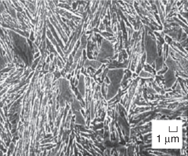
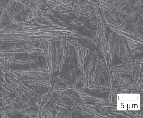
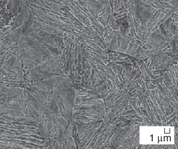
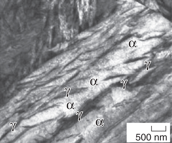
750ºC. Microstructural characterization
revealed that the nickel alloyed
steels in Table I had the desired microstructure
consisting of carbide-free
upper bainite (α phase) with interlath
high carbon (~1 wt.% carbon) retained
austenite films (γ phase) (Figure 1).15 The two steels achieved the highest
combination of strength and toughness
for bainitic microstructures. Toughness
values of nearly 130 MPa m1/2 were
obtained for strength in the range of
1,6001,700 MPa.15 This work demonstrated
experimentally that models
based on phase transformation theory
can be successfully applied to the design
of carbide-free bainitic steels.
Newly Designed Bainitic Steels
Containing Manganese
More recently, a new set of alloys
was designed to have the same bainitic
transformation region in the TTT diagram
and the same T'o curve as those
of Ni2 bainitic steel,16 while avoiding
nickel additions for economic reasons.
The chemical composition of the new
alloys was selected to have tdispl and Vb at 400ºC similar to those of Ni2
steel. Both parameters define bainite
transformation according to thermodynamics.7
Moreover, tdif must be high
enough to avoid the formation of proeutectoid
ferrite during cooling. The
chemical compositions of the new designed
steels are given in Table I. Calculated
TTT diagrams suggested that a
two-step cooling schedule is the most
promising processing route to obtain a
full bainitic microstructure in the new
alloys. An initial rapid cooling (at least
30ºC/s) should be performed to avoid
the formation of proeutectoid ferrite
during cooling. The cooling rate should
be decreased (around 0.5ºC/s) before Bs
temperature is reached (around 500ºC),
in order to cross the bainitic zone of the
TTT diagram. According to the kinetic
model, a full bainitic microstructure
(volume fraction of bainite higher than
0.75) will be formed by applying this
two-step cooling schedule after finishing
rolling.
The proposed alloys were prepared
in a 60 kg vacuum induction furnace.
Samples were hot rolled to ~12 mm in
several passes, finishing at 930ºC. The
desired bainitic microstructure was obtained
in all the steels by air cooling
from different temperatures after an
initial accelerated cooling at 70ºC/s.
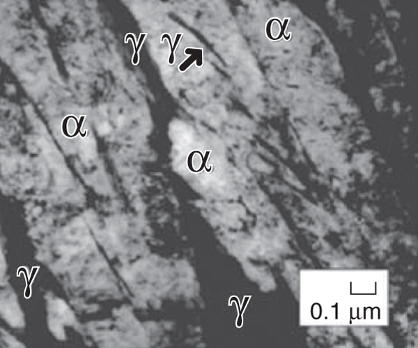
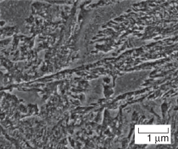
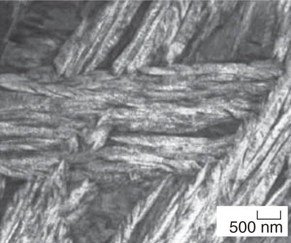
Experimental data on the microstructure
are presented in Table II. Scanning
and transmission electron micrographs
(SEM and TEM) of fully carbide-free
bainitic microstructures (more than
75% of bainitic ferrite) in the four designed
steels are shown in Figure 2. Microstructural
characterization revealed
that the CENIM 14 alloys, after air
cooling from every temperature tested,
have the desired microstructure consisting
of carbide-free upper bainite. Due
to the high volume fraction of bainitic
ferrite in those samples, retained austenite
is present as films between the
subunits of bainitic ferrite. Both phases
are free of carbides, as the TEM micrographs
confirm.
Table II. Quantitative Data on Microstructure
and Hardness of the Designed Steels
|
| Steel / FCT |
VB |
VM |
Vγ |
xγ (wt.%) |
HV30 |
Ni2 (Reference) |
0.81 ± 0.06 |
0.08 ± 0.05 |
0.11 ± 0.01 |
1.03 ± 0.03 |
536 ± 6 |
CENIM 1 / 450ºC |
0.73 ± 0.04 |
0.24 ± 0.05 |
0.03 ± 0.01 |
0.66 ± 0.06 |
530 ± 7 |
CENIM 1 / 600ºC |
0.76 ± 0.03 |
0.21 ± 0.04 |
0.03 ± 0.01 |
0.95 ± 0.01 |
522 ± 4 |
CENIM 2 / 500ºC |
0.77 ± 0.04 |
0.13 ± 0.05 |
0.10 ± 0.01 |
1.14 ± 0.03 |
519 ± 3 |
CENIM 2 / 550ºC |
0.80 ± 0.04 |
0.09 ± 0.05 |
0.10 ± 0.01 |
1.26 ± 0.07 |
460 ± 20 |
CENIM 3 / 500ºC |
0.88 ± 0.02 |
0.02 ± 0.03 |
0.11 ± 0.01 |
1.03 ± 0.05 |
495 ± 15 |
CENIM 3 / 550ºC |
0.88 ± 0.02 |
0.03 ± 0.04 |
0.11 ± 0.01 |
1.04 ± 0.04 |
505 ± 6 |
CENIM 4 / 500ºC |
0.88 ± 0.02 |
0.09 ± 0.04 |
0.03 ± 0.01 |
1.26 ± 0.07 |
531 ± 10 |
FCT is interrupted accelerating cooling temperature; VB is the volume fraction of bainitic ferrite; VM is the volume fraction of
martensite; Vγ is the volume fraction of austenite; xγ is the carbon content in austenite.
|
The corresponding mechanical properties
are reported in Table III together
with those for the reference material
(Ni2 steel). The values presented are
the averages of three tests. The tensile
tests were performed at room temperature
and low strain rate (0.008 s1).
Plates of bainitic ferrite are typically
10 µm long and ~0.2 µm thick (see the
TEM micrographs in Figure 2). This
morphology gives a small mean free
path for dislocation glide. Thus, the
main microstructural contribution to
the strength of bainite is from the extremely
fine grain size of bainitic ferrite.
It is difficult to separate the effect
of retained austenite on the strength of
these steels from other factors. Qualitatively,
austenite can affect the strength
in several ways. Residual austenite can
transform to martensite during cooling
to room temperature.11,12
In addition,
retained austenite interlath films can
increase the strength by transforming
to martensite during testing, similar to the behavior of transformation-induced
plasticity steels.11,12 Tensile elongation
is controlled by the volume fraction of
retained austenite. Retained austenite is
a ductile phase compared to the bainitic
ferrite and would be expected to enhance
ductility provided the austenite is
homogeneously distributed along plate
boundaries (film austenite). However,
isolated pools of austenite (blocky austenite)
would have an unfavorable result
on both elongation and strength.
From Table III, it is clear that the steels
possess a combination of high strength
and good ductility.
Impact toughness was measured on
normalized Charpy notched (10 mm2 ×
10 mm2) samples at 20ºC with the use
of a 300 J Charpy testing machine.
Charpy impact test results are also listed
in Table III for all alloys. A considerable
improvement in toughness is
obtained when the volume fraction of
bainite increases in the microstructure.
The results are consistent with the enhancement
of toughness expected when
the amount of blocky austenite and
martensite are reduced and, in general,
when the thermal and mechanical stability
of residual austenite is increased.
Low-Temperature Bainite:
From Micro to Nano
A combination of the models described
above was used to produce the
finest possible bainitic microstructure
by transformation at the lowest possible
temperature. From the models, NANOBAIN
steel (Table I) was proposed to
decrease bainite transformation temperatures,
increase the maximum volume
fraction of bainite in the final microstructure,
and to improve the hardenability
of the steels. The carbon concentration
was selected from calculations
to suppress Bs temperature and to
make austenite stronger, with the aim
of obtaining extremely thin platelets of
bainite. Samples were supplied as 30
kg cast ingots. They were first homogenized
at 1,200ºC for two days in partially
evacuated quartz capsules flushed
with argon. Afterward, the sealed samples
were cooled in air. The homogenized
specimens were then austenitized
for 15 min. at 1,000ºC, and isothermally
transformed at temperatures ranging from 125ºC to 500ºC for different
times before quenching into water.
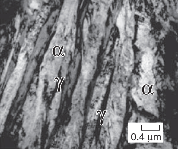
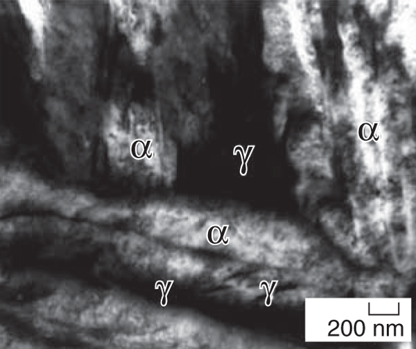
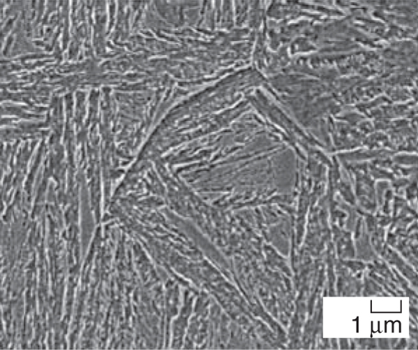
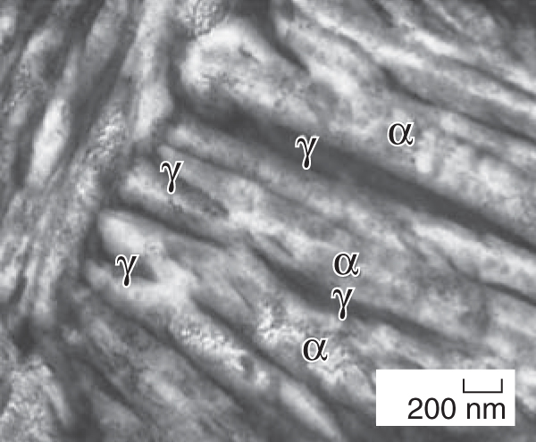
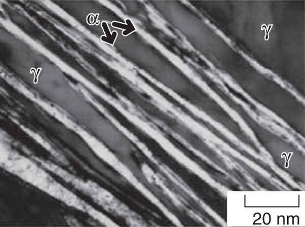
A transmission electron micrograph
of NANOBAIN transformed at 200ºC
for 15 days is presented in Figure 3.
Some of the plates of bainite are incredibly
thin (2040 nm) and long, giving a
fine scale structure consisting of an intimate
mixture of austenite and ferrite.
Dislocation debris is evident in both the
bainitic ferrite and the surrounding austenite.
Extensive TEM failed to identify
carbides in the microstructure; only a
few extremely fine (20 nm wide and
175 nm long) cementite particles in the
bainitic ferrite were found in samples
transformed at 190ºC for 14 days.17 Quite remarkably, the bainite plates
formed at 200ºC (Figure 3) have a
width that is less than 50 nm, with each
plate separated by an even finer film of
retained austenite. The small thickness
of bainitic ferrite plates in low-temperature
bainite leads to hardness values in
excess of 600 HV and strengths in excess
of 2.5 GPa.17
Theory indicates that the largest effect
of bainite plate thickness is due to
the strength of the austenite, the free
energy change accompanying transformation,
and a small independent effect
due to transformation temperature.18 In
this case, the observed refinement is
mainly a consequence of the effect of
high carbon content and the low transformation
temperature on increasing
the strength of the austenite.
Table III. Tensile Properties and Charpy Impact Test Results at 20ºC
|
| Steel / FCT |
VB (MPa) |
UTS (MPa) |
TE (%) |
Impact Energy |
|
Ni2 (Reference) |
1,054 ± 49 |
1,523 ± 21 |
25 ± 1 |
50 ± 1 |
CENIM 1 / 450ºC |
1,240 ± 31 |
1,796 ± 21 |
18 ± 1 |
36 ± 2 |
CENIM 1 / 600ºC |
1,204 ± 29 |
1,701 ± 9 |
16 ± 1 |
22 ± 1 |
CENIM 2 / 500ºC |
1,187 ± 16 |
1,606 ± 30 |
17 ± 2 |
36 ± 2 |
CENIM 2 / 550ºC |
1,128 ± 32 |
1,539 ± 21 |
16 ± 1 |
44 ± 2 |
CENIM 3 / 500ºC |
1,194 ± 35 |
1,652 ± 6 |
18 ± 1 |
44 ± 1 |
CENIM 3 / 550ºC |
1,204 ± 18 |
1,642 ± 12 |
18 ± 1 |
46 ± 2 |
CENIM 4 / 500ºC |
1,339 ± 16 |
1,763 ± 18 |
16 ± 1 |
38 ± 1 |
FCT is interrupted accelerating cooling temperature; YS yield strength; UTS ultimate tensile strength; TE total elongation.
|
Initially, transmission electron microscopy
was unable to reveal carbide
particles inside the bainitic ferrite;
however, after a large and equivalent
set of accumulated atom probe results,
the presence of cementite has been confirmed
as the lower bainite carbide despite
the high carbon and high silicon
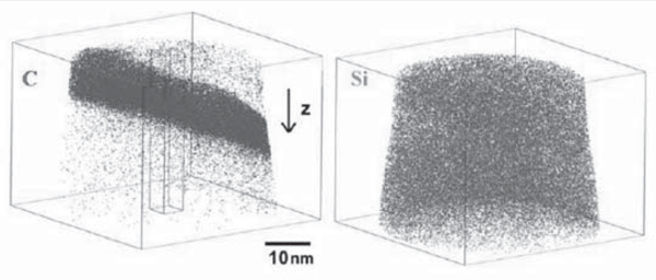
content of the steel used. An example
of carbide particle precipitated inside
bainitic ferrite for a sample transformed
at 300ºC for 8 hours is shown in carbon
and silicon atoms maps in Figure 4
from atom probe measurements. The
measured carbon level (~25 at.%) allows
the type of carbide precipitated
inside bainitic ferrite to be identified as
cementite (i.e., 25 at.% for cementite
versus 30 at.% for ε-carbide). It is clear
from these results that para-cementite
is observed (i.e., cementite formed with
the same Fe/M atom ratio as the matrix,
where M is a substitutional atom such
as silicon).19
Since silicon does not partition
and is expected to favor the precipitation
of ε-carbide, the absence of
ε-carbide precipitation in this high-carbon
bainitic steel can be only rationalized
in terms of carbon trapping at dislocations
as in the theory of tempering
due to Kalish and Cohen.20 Atom probe
tomography also revealed that this exacess of carbon was trapped at dislocations
in the vicinity of the ferrite/austenite
interface. As a result, the carbide
precipitation sequence is modified.21
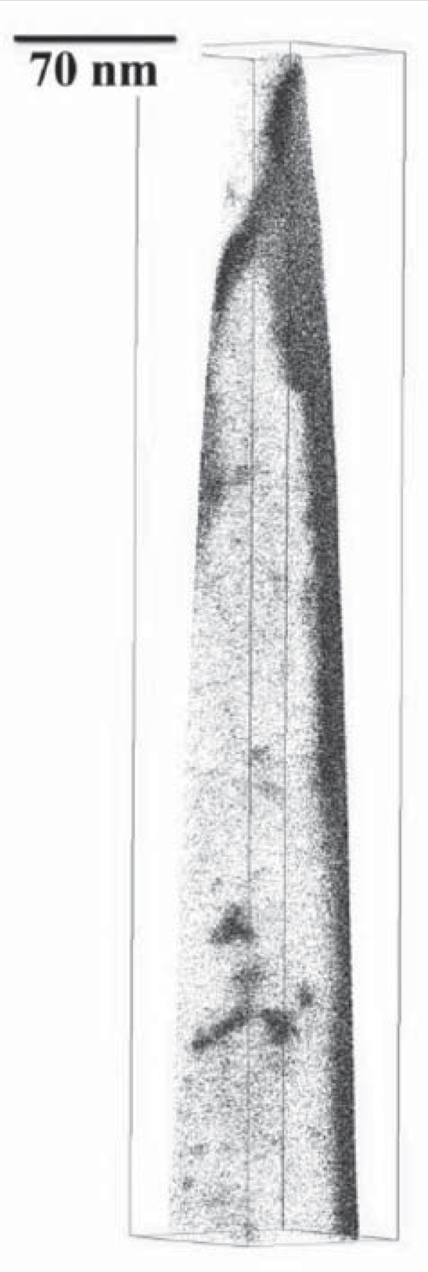
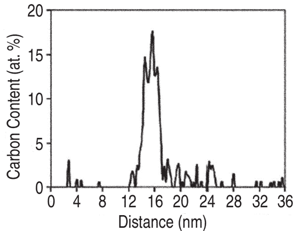
Moreover, carbon atom maps and concentration
profiles of bainite at early
stages of tempering (400ºC for 30 min.)
clearly show the presence of carbonenriched
regions, randomly dispersed
throughout a carbon-depleted ferrite
matrix, as presented in Figure 5. These
clusters are ~6 nm thick and have a
maximum carbon content of ~14 at.%.
Such fluctuations of solute concentration
may be associated with the solute
redistribution to dislocations in bainite,
as explained above. These regions may
be gradually replaced by regions even
more highly enriched in carbon, signifying
the onset of ε-carbide precipitation
as the tempering temperature is
increased.22
CONCLUSIONS
The alloys designed in this work
present the highest strength/toughness
combinations ever recorded in bainitic
steels. These alloys show better mechanical
properties of the quenched and
tempered low-alloy martensitic steels
and match the critical properties of
maraging steels, which are at least thirty
times more expensive. Moreover,
this work has revealed that it is possible
to obtain bainite by transforming at
very low temperatures.
This has the
consequence that the plates of bainite
are fine-scale, 2040 nm thick, so that
the material becomes very strong.
When this feature is combined with the
fact that the plates of ferrite are interspersed
with austenite, it becomes possible
to create strong and tough steels.
Although the results themselves are exciting,
the potential for commercial exploitation
is large because the alloys are
very inexpensive and easy to manufacture.
ACKNOWLEDGEMENTS
The authors gratefully acknowledge
the support of Spanish Ministerio de
Ciencia y Tecnología Plan Nacional de
I+D+I (20042007) funding this research
under the contract MAT2007
63873. All of the authors want to thank
Arcelor Research for manufacturing
the designed alloys. Research at the
Oak Ridge National Laboratory SHaRE
User Facility was sponsored by the Scientific User Facilities Division, Office
of Basic Energy Sciences, U.S. Department
of Energy. The authors also would
like to express their special acknowledgement
to Prof. H.K.D.H. Bhadeshia
for helpful discussions.
REFERENCES
1. H.K.D.H. Bhadeshia and D.V. Edmonds, Met. Sci., 17
(1983), pp. 411419.
2. H.K.D.H. Bhadeshia and D.V. Edmonds, Met. Sci., 17
(1983), pp. 420425.
3. H.K.D.H. Bhadeshia and D.V. Edmonds, Acta Metall.,
28 (1980), pp. 12651273.
4. H.K.D.H. Bhadeshia,Acta Metall., 29 (1981), pp.
11171130.
5. C. García-Mateo and H.K.D.H. Bhadeshia, Mat. Sc.
and Eng., 378A (2004), pp 289292.
6. Materials Algorithms Project (MAP), Department of
Materials Science and Metallurgy, University of Cambridge,
U.K.: http://www.msm.cam.ac.uk/map.
7. H.K.D.H. Bhadeshia, Met. Sci., 16 (1982), pp. 159
165.
8. S.J. Jones and H.K.D.H. Bhadeshia, Acta Metall., 45
(1997), pp. 29112920.
9. S.V. Parker, Modelling of Phase Transformation in
Hot Rolled Steels (Ph.D. thesis, University of Cambridge,
U. K., 1997).
10. F.G. Caballero, C. Capdevila, and C. García de Andrés, Mat. Sci. Technol., 18 (2002), pp. 534540.
11. V.T.T. Miihkinen and D.V. Edmonds, Mater. Sci.
Technol., 3 (1987), pp. 422431.
12. V.T.T. Miihkinen and D.V. Edmonds, Mater. Sci.
Technol., 3 (1987), pp. 432440.
13. V.T.T. Miihkinen and D.V. Edmonds, Mater. Sci.
Technol., 3 (1987), pp. 441449.
14. F.G. Caballero et al., Mat. Sci. and Technol., 17
(2001), pp. 512516.
15. F.G. Caballero et al., Mat. Sci. and Technol., 17
(2001), pp. 517522.
16. F.G. Caballero et al., ISIJ Inter., 46 (7) (2006), pp.
14791488.
17. F.G. Caballero et al., Mater. Sci. Technol., 18 (2002),
pp. 279284.
18. S.B. Singh and H.K.D.H. Bhadeshia, Mater. Sci.
Eng., 245A (1998), pp. 7279.
19. S.S. Babu, K. Hono, and T. Sakurai, Metall. Mater.
Trans., 25A (1994), pp. 499508.
20. D. Kalish and M. Cohen, Mater. Sci. Eng., 6 (1970),
pp. 156166.
21. F.G. Caballero et al., Acta Metall., 55 (2007), pp.
381390.
22. K.A. Taylor et al., Metall. Mater. Trans., 20A (1989),
pp. 27492765.
F.G. Caballero, C. Garcia-Mateo, C. Capdevila, and
C. Garcia de Andrés are with Centro Nacional de
Investigaciones Metalúrgicas (CENIM-CSIC); Avda
Gregorio del Amo, 8; Madrid, E-28040, Spain; M.K.
Miller is with Oak Ridge National Laboratory, Materials
Science and Technology Division, P.O. Box
2008; Oak Ridge, TN 37831-6136. Dr. Caballero can
be reached at fgc@cenim.csic.es.
|
 Presenting a Web-Enhanced