|
This paper aims to give a broad overview
of the challenges that are faced
in load-bearing medical devices and
focuses specifically on the challenges
faced in utilizing polymeric materials
in such applications. Three specific
cases are given in the field of polymeric
biomaterials. These cases build in complexity
and initiate with examination of
the evolution of intravascular catheter
design in which the materials, properties,
and processing have been optimized
to develop a system that can be
used in an angioplasty procedure with
little concern of clinical failure.
INTRODUCTION
In the field of biomaterials there are
a number of challenges that must be
addressed for successful design of a
medical implant.15 First, all biomaterials
must be biocompatible and, unless
the material is designed to degrade in
the body, it must offer long-term resistance
to biological attack in vivo. Biocompatibility
is a complex issue in that
both the composition and size scale of
the biomaterial can dictate the cellular
response in vivo. Bulk materials that are
considered biocompatible can become
bioactive or trigger an inflammatory
response if the material is present in
small enough particles to be ingested by
macrophages or elicit cellular interactions.6,7 Many implants can be susceptible
to premature failures due to biological
attack, and this limits the choice of
materials that can be safely used in the
body. In fact, much of the material evolution in metals used in the body is built
upon the improvement of corrosion resistance.
Load-bearing devices face the
challenge of a coupled effect between
the structural requirements of the implant
and the aggressive environment
of the body. Many metallic systems
employed today are still susceptible
to stress corrosion cracking or crevice
corrosion when the stress state, implant
design, and biological environment are
coupled.8 Polymers offer the benefit of
being intrinsically resistant to environmental
attack; however, polymeric biomaterials
face unique demands when
utilized in load-bearing medical devices
in that the mechanical stresses in which
they function often put them at direct
risk for yield, fatigue, wear, creep, and
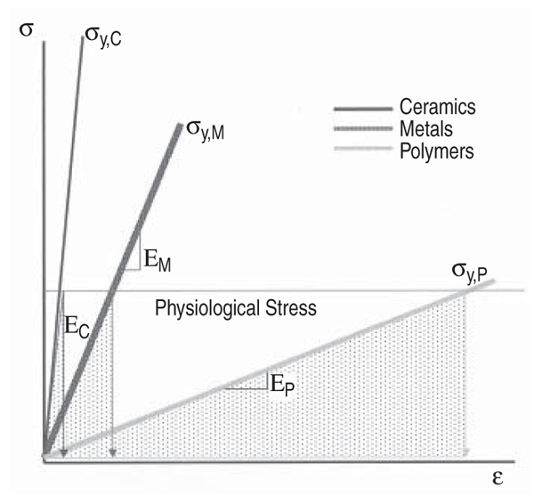
fracture. Figure 1 illustrates how many
polymers are loaded to a stress value
near their yield strength when subjected
to the physiological stress state of the
implant; this is in contrast to metals and
ceramics that typically operate well below
their strength levels.
Medical devices composed of polymers,
like other biomaterial systems, are
not immune to mechanically induced
biological failures.1,2 The functional demands
placed on an implant may elicit
mechanical damage that is sufficient to
liberate particulates or other constituents
that can trigger a chronic inflammatory
response in vivo, ultimately
leading to the biological failure of the
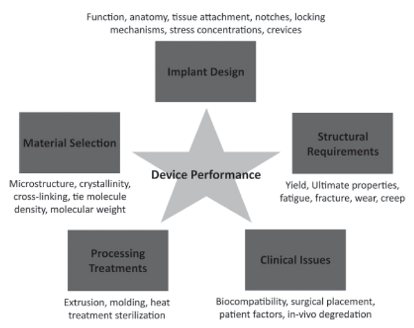
device. The performance of a medical
device is quite complicated as there are
several contributing and related factors,
including the implant design, material
selection, structural requirements
of the device, processing or manufacturing
modality of the implant, and
clinical issues. Figure 2 illustrates the
contributing factors that affect device
performance. These issues contribute to a multifactorial problem that often requires
numerous iterations in the device
design with a continuous feedback process
that relies on assessment of device
performance in its clinical application.
An additional challenge in the medical
device field is that it is extremely difficult
to model the actual in-vivo conditions
and thus bench tests rarely predict
clinical performance of the implant.
In the past several decades a plethora
of research has addressed the role of
processing and microstructure on mechanical
behavior of polymers that are
utilized in the body.1 However, a paucity
of studies have addressed the intricate
relationships that exist between
structure, properties, processing, clinical
conditions, and device design. Thus
while some aspects of medical device
design are well established others remain
inchoate. Often device manufacturers
seek to improve a specific property
or function of a device without appreciating
the tradeoffs in other areas of
performance. For instance, a change in
material can result in unpredicted failures
of an implant if the device design
is not updated and/or verified to meet
its functional requirements. In general
any time one factor is shifted there is a
tradeoff elsewhere.
Predicting the ultimate consequences
of performance tradeoffs is rarely a
simple task, given the complex interplay
of variables, and yet it is critical
to the development of devices that offer
long-term performance in vivo.
Thus, there is a need for a fundamental,
mechanistic understanding of polymeric
biomaterials science and how it
is tied to processing, properties, device
design, and clinical performance. This
work addresses the general functional
requirements for a number of medical
device applications utilizing polymers.
Three specific examples in the medical
device field are examined where the
design, material, process, or properties
have evolved in a systematic way.
MEDICAL POLYMERS IN LOAD-BEARING DEVICES
Medical polymers are used in a
broad range of applications including
tissue repair and replacement, drug delivery,
and wound healing.1 Polymers
are capable of a wide range of structural
properties that depend on backbone
structure, molecular weight, entanglement
density, degree of crystallinity,
and degree of crosslinking.9 In general,
polymers exhibit time-dependent mechanical
behavior and are known to be
viscoelastic. For example, the elastic
modulus and yield strength of a polymer
generally increases with increasing
strain rate while the strain to failure
typically decreases with increased loading
rates. Similarly, sustained loads can
result in time-dependent strain or creep
in polymers. Time-dependent material
properties render the prediction of invivo
performance challenging, particularly
when the load conditions become
complex. In fact, load-bearing medical
devices often subject the polymer components
to their limits of yield, fracture,
wear, and fatigue resistance. Table I
presents several applications of polymers
in load-bearing implants.
| HOW WOULD YOU... |
describe the overall significance
of this paper?
Medical implant design is a multifactorial
process involving the
interplay of material structure
and properties, processing,
biocompatibility concerns, and
long-term mechanical reliability.
Design iterations may have
unforeseen clinical consequences
that necessitate further analysis or
development. This paper introduces
biomedical polymers and describes
the incremental design evolution
and material optimization of three
polymeric medical devices.
describe this work to a
Load-bearing polymeric medical
implants can be expected to function
for decades, while experiencing
stresses near or beyond their
strength. Further, mechanical
damage can release particulate
debris or leached constituents that
may elicit a severe immune response
from the body. The interplay of
mechanical, biological, and material
performance in a medical implant
is sophisticated, particularly given
that the environment in the body
is diffi cult to model. This paper
describes the design evolution of
and performance trade-offs in three
polymeric medical implant systems.
describe this work to a
layperson?
Medical implants made of polymers
(plastics) are often subjected to
relatively severe forces. These forces
may break down the material over
time, possibly causing the implant
to break or resulting in a biological
reaction that causes the body to
reject the implant. This paper
describes the design evolution of
three polymeric medical implant
systems, based on incremental
improvement and trade-offs. |
STRUCTURE PROPERTY DESIGN RELATIONSHIPS
Understanding structure-property design
relationships is essential for the
successful performance of a medical
implant. Yet, implants often undergo iterative
changes in design, materials selection,
and processing, resulting from
the study of their overall clinical performance.
Sometimes challenges can be
adequately addressed in the laboratory,
but often feedback from the clinical use
of the device is key to understanding
the factors at play. In this section we
detail three cases where the design, material,
process, or functional properties
have evolved in a systematic way in the
medical device industry. These cases
include an intravascular balloon catheter
in which the materials, properties,
and processing have been optimized to
develop a system that can be used in an
angioplasty procedure with little concern
of clinical failure; silicone breast
implants, which have utilized a shift in
design and materials to develop more
robust and leak-resistant implants; and
total hip replacements, where a shift in
material properties without a change in
design enabled catastrophic fracture of
the polymer bearing component.
Intravascular Balloon Catheters
Intravascular catheters are widely
used in both diagnostic and interventional
procedures. Balloon catheters are
probably best known for their clinical
success in coronary angioplasty.10 In
such applications the balloon at the distal
end of a catheter is inflated to open
an occluded blood vessel afflicted with
heart disease. Such systems are also
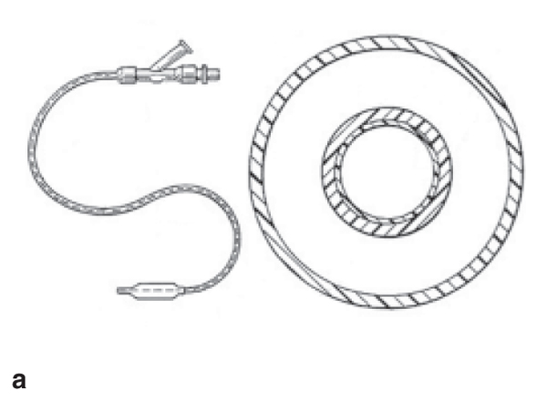
used in stent deployment and Figure 3
shows a rendition of a catheter balloon
used in the deployment of a coronary
stent for the repair of an occluded artery.11 There are a few important functional
requirements for the polymeric
balloon: its profile must be small enough
to be navigated through the coronary
arteries; it must provide sufficient radial
force to open an occluded vessel, deploy
a stent, or in some instances it may
need to exert a radial force on a highly
calcified plaque; and it must withstand
the inflation pressures necessary for the
clinical procedure without rupturing.
For these reasons most polymeric catheter
balloons are typically made of
polyester or nylon due to their tensile
strengths and ease of processing.
An intravascular balloon catheter
system used in coronary angioplasty is
typically inserted through the femoral
artery and then it is navigated through
the tortuous vasculature to its final destination
in the heart. Due to the anatomical
requirements there are a number of
unique functional requirements for intravascular
catheter systems. Intravascular
catheters are generally constructed of a long tube with an inner opening
or lumen that accommodates the guide
wire that delivers the balloon to its final
destination and that facilitates an
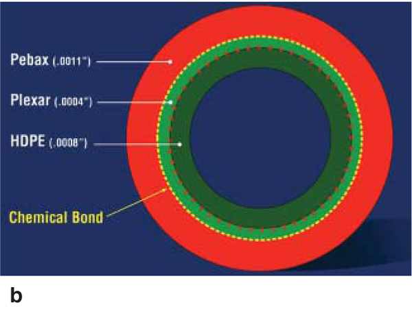
inflation mechanism. Figure 4a shows
a schematic illustration of a balloon
catheter system and its cross section
and Figure 4b shows a specific cross
section in a modern catheter comprised
of a high-density polyethylene (HDPE)
inner layer, an outer layer of polyester
(Pebax®), and a functionalized lowdensity
polyethylene tie layer (Plexar®)
that facilitates bonding between the two
layers.
In designing the catheter shaft it is
ideal to make the system in such a way
that it can readily navigate the tortuosity
inherent to the vascular system without
kinking or penetration of the tissue.
In order to maneuver through the anatomy,
the catheter tube needs to provide
flexibility to follow the desired path of
the surgeon. This functional property is
referred to as trackability. The catheter
tube must also have sufficient axial
stiffness to travel along the winding
path of the vasculature. Additionally the
catheter tube should offer resistance to
twisting or in transmitting torque from
the proximal to distal (balloon) end; this
property is termed torqueability.11
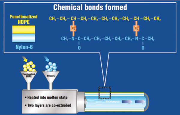
Initial catheter tubes were made of
a single polymeric material such as
nylon, polyethylene, or polyethylene
terephthalate, but these polymers were
limited by their relatively high coefficients
of friction. In an iteration of design,
these polymers were coated with
silicone to achieve the desired coefficient
of friction, however, these systems
were limited in their ability to deliver
sufficient trackability and torqueability.
Subsequent designs moved toward
a co-extruded system using two different
polymers: HDPE for the inner tube
that rides over the guide wire and a nylon
or polyester outer tube that can be
chemically or thermally bonded to the
distal balloon. In its basic form HDPE
does not form a chemical bond with a
nylon or polyester material, and consequently
these systems were also prone
to delamination. In order to solve this
material-processing-performance problem,
the use of a chemical functional
group that could be copolymerized
with the HDPE was used to achieve a
chemical bond between the two distinct
polymers. The use of functional groups
or tie layers evolved the intravascular
catheter tube into a system that could
offer the required functional properties
without delamination and could be
readily manufactured using a co-extrusion
process (Figure 5).
Modern vascular catheters either use
functional groups or tie layers to facilitate
bonding between the inner HDPE
and the outer polyester or nylon material,
as shown in Figure 4b. Such systems
offer good structural integrity, deliver
the required functional properties, and
minimize complications due to delamination
between the materials. Thus, the
design evolution of the modern catheter
system involved several iterations
of materials selection, processing, and
design to achieve the functional requirements
of the intravascular balloon
catheter in a clinical setting. This is an
example of where design iterations that
have transpired over several decades
have resulted in the evolution of a very
reliable biomedical device.
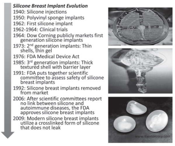
Silicone Breast Implants
Silicone has been utilized in breast
implants since 1962; however, early
designs were prone to rupture and leaking.12 The first implants utilized low viscosity
forms of silicone gel encased in
a solid silicone elastomer shell but were
prone to failure through tissue contracture
around the implant or rupture.1214
Rupture of the implant shell enabled the
silicone to leak into the surrounding tissue,
which could then elicit a chronic
inflammatory response. Over the next
20 years, second and third generations
of breast implants experimented with
different silicone gels and encasement
designs to minimize or prevent leaks
and inflammatory complications. While
these implants were a vast improvement
over previous design iterations, leakage
and rupture were still major problems.
Many of the early designs and materials
used were prior to the 1976
Medical Device Act that provided the
Federal Drug Administration (FDA)
the authority to review and regulate
medical devices.4 Without any formal
regulation, companies could switch materials
used in their devices without the
need of FDA approval. Thus, the earlier
silicone breast implant designs were not
subjected by the FDA to the scrutiny of
structural assessment and biocompatibility
testing that newer devices must
undergo prior to approval for clinical
use. In the early 1990s, extensive litigation
and research into the realm of silicone
breast implant safety ensued with
great controversy. The premise of these
lawsuits was that leaking of silicone
would lead to connective tissue disease,
immune reactions, and ultimately autoimmune
disorders.15
The FDA put together a scientific
committee to assess the integrity and
medical concerns surrounding breast
implants in 1991, while mandating the
withdrawal of silicone implants for cosmetic
use until the investigation of the
scientific committee was complete.14
In 1999, the scientific committee concluded
that silicone breast implants
were not responsible for the immunological
diseases that had been rampant
in many patients who had the silicone
implants.15 In 2006, the FDA approved
the re-release of silicone breast implants
utilizing a crosslinked form of
the polymer, under the conditions that
patients must be at least 22 years of age
and would require an MRI in the first 3
years and then every 2 years thereafter.
The current view is that these implants
will not likely last a lifetime as initially
promised in the early release of
silicone implants, and women should
plan to have multiple surgeries.16
Modern silicone breast implants
have evolved in design to ensure safety
against rupture and leakage. The primary
mechanical design requirement
of a breast implant is resistance to
rupture. This is typically modeled as a
thin-walled pressure-vessel to address
the stress resulting from peak compressive
forces. The primary design change
from the first implants has been in the
utilization of a crosslinked form of silicone
that does not leak if the surrounding
shell is ruptured or torn. Figure 6
shows the design evolution of silicone
implants and provides an image showing
the consequences of rupture when
the silicone has low viscosity. In the
modern silicone implant the implant retains
its structural integrity and does not
leak into adjacent tissue.
However, several concerns linger in
the wake of the recent FDA approval
of silicone implants. One concern is
founded upon prior clinical complications
of leaking and association with
autoimmune disease. While scientific
studies have shown no link between
silicone and autoimmune disease, much
of the public at large remains cautious.
Also, while a large number of clinical
studies have been undertaken to demonstrate
the safety of silicone implants,
the long-term performance of these implants
has not been established.
This is an example of a design iteration
process where the clinical performance
has driven the research for optimization
of materials selection and
design of the implant to ensure safety.
As with all devices, the clinical performance
drives a continuous feedback
loop, and it will be years before the
long-term performance of crosslinked
silicone breast implants is understood.
Ultra-High-Molecular-Weight
Polyethylene in Total Hip
Replacements
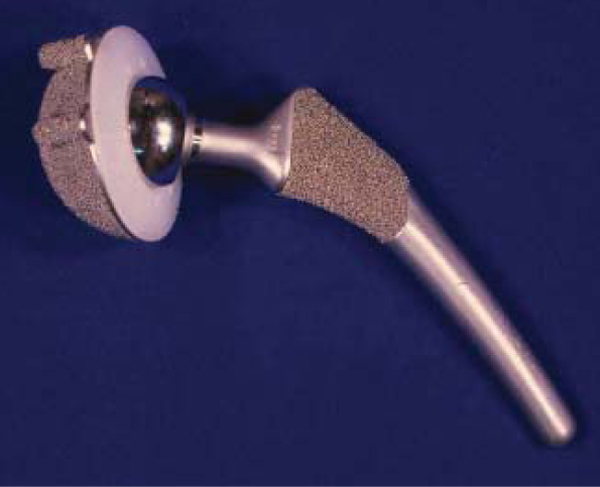
The designs and materials used in
total hip replacements have been under
steady improvement for nearly 50 years,
and currently enjoy a high degree of
success with an estimated 90% survival
rate after 10 years in vivo as the result
of this effort.17 In total hip arthroplasty,
the bearing system typically employs
an ultra-high-molecular-weight polyethylene
(UHMWPE) insert that articulates
against a cobalt-chromium alloy
or ceramic in order to restore function
to a damaged or diseased joint. The majority
of total hip replacement systems
in use today utilize a modular design,
where the UHMWPE bearing is assembled
to a metal shell that integrates with
the bone of the acetabulum of the pelvis
(Figure 7). The UHMWPE component
must be held in place by a combination
of locking mechanisms and interference
fitting. Locking mechanisms often
take the form of notches or grooves
that cause a stress concentration during
loading of the implant, and are located
where the component can experience
substantial tensile stress. Such design
features are a potential structural concern,
particularly for a relatively flaw-intolerant
material such as UHWMPE.
One of the primary clinical concerns
in total hip replacements is wear-mediated
osteolysis, in which inert microscopic
wear debris from the bearing
cause an acute immune response that results in bone lesions that can compromise
the implant.1820 In the last decade,
the mitigation of wear volume has been
the main focus of technical development,
and the principal breakthrough in
that area has been the use of ionizing
radiation to crosslink the UHMWPE
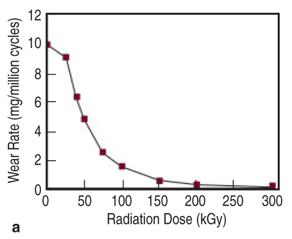
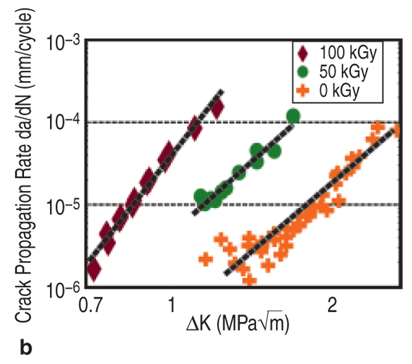
bearing for improved wear resistance.
Crosslinking of UHMWPE has been
shown to reduce the volume of evolved
wear particles in pin-on-disc and in vitro
implant simulator studies, with a dose-dependent
relationship, as shown in
Figure 8a.21 This effect saturates around
100 kGy of radiation, when the polymer
is termed highly crosslinked. Combined
with a post-irradiation annealing
or melting step to eliminate free radicals,
crosslinking substantially reduces
the strength, ductility, toughness, and
fatigue crack propagation resistance of
UHMWPE.22 Thus, mitigating wear via
radiation crosslinking results in a tradeoff
against other material performance
characteristics, such as fatigue crack
propagation resistance (Figure 8b).22
Performance Tradeoffs in Total
Hip Replacements
There are performance tradeoffs in
total hip replacements owing to the
benefit of improved wear resistance
at the expense of fatigue fracture in
crosslinked UHMWPE. In fact, recent
failure analyses of highly crosslinked
UHMWPE hip replacement components
have indicated that these systems
are susceptible to fracture in a clinical
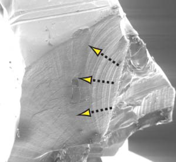
environment.23,24 The authors analyzed
the clinical failure of four catastrophically
fractured, crosslinked acetabular
liners to elucidate this performance
tradeoff.24 Each implant was designed
and manufactured by a different device
manufacturer, but shared similar
design features: an unsupported rim
outside the main weight-bearing region
containing notches or interfaced with a notch in the metal shell. Another critical
aspect these implants shared was
that they were all developed originally
for uncrosslinked UHMWPE, and subsequently
deployed with crosslinked
UHMWPE without updating the design
to reflect the consequent reduction in
defect tolerance.
The failure analysis sought to clarify
whether the mechanical compromise
resulting from crosslinking might have
been sufficient to enable the observed
fractures. Fractography results demonstrated
that the fractures in each case
initiated in a microscopically similar
manner, at the root of a stress-concentrating
feature, despite their different
designs and clinical case histories. The
fracture surfaces exhibited faint lines
parallel to the advancing crack front,
originating at a point on the outside
surface of the component near the focus
of a stress concentration. Near the
initiation site, these surface features
were prominent and resembled clamshell
markings, propagating in a roughly
radial or thumbnail morphology. A
representative initiation site is shown in
Figure 9, where the procession of clam
shell markings is distinctly visible.24
The apparent fractographic similarity
of the crack initiation sites was taken
as strong evidence in support of a common
failure mechanism among the four
components, and thus the failures were
likely derivative of their common material
and design attributes.
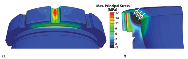
A finite element analysis was then
conducted of each liner to predict the
stress generated during a 500 N direct
loading event of the exposed rim.
One representative result is given in
Figure 10.24 This analysis showed that
the resultant maximum principal stress
peaked at the root of the notches, near
where the cracks initiated. This principal
stress exceeded that necessary for
incipient propagation of a 2 mm deep
notch with an incipient crack in each
case, using a stress intensity inception
value to depict the conditions for
the onset of crack growth. This finding
was interpreted to indicate that the peak
principal stress was sufficient to propagate
initiated cracks at the observed initiation
sites. Thus the authors concluded that direct rim loading is a sufficient
condition to propagate cracks beyond a
rim notch and lead to the observed catastrophic
fractures.
The finite element analysis also predicted
that the stress rapidly decayed
with depth from the surface of the rim
notch in each case (Figure 10). Thus,
while the stress was severe enough for
incipient propagation near the surface,
a short distance of growth could put a
crack outside the notch-affected zone
and lead to crack arrest. As the majority
of acetabular liners experience substantial
rim loading events,25 we therefore
hypothesized that a substantial fraction
of intact crosslinked acetabular liners
should harbor at least one initiated fatigue
crack near an elevated rim notch.
A subsequent investigation of intact retrieved
crosslinked liners reported that
six of nine inspected liners harbored
initiated cracks.26 These results motivate
the need to understand crack initiation
in existing and future designs of
UHMWPE acetabular liners.
Design for Crack Initiation
Resistance
The crack initiation resistance of a
UHMWPE component is governed by
intrinsic material behavior, extrinsic design,
and clinical factors. The material
and design characteristics of importance
depend on the physical model used to
describe crack initiation. The viscous
flow of the highly stressed material at
a notch or crack tip has been proposed
as the dominant deformation fracture
mechanism in UHMWPE.27,28 A crack
initiation framework, based on viscoplastic
behavior,29 can be used to evaluate
tradeoffs in performance related to
material behavior and design features.
For materials that obey a power-law
creep relation, a constant load yields
the same time dependence of energy
release rate (J-integral) at a crack tip or
notch root. This equation, shown below,
implies that the J-integral monotonically
increases with time under load, such
that a sub-critical value will eventually
overcome a threshold for crack initiation,
Jc. Thus, one can find the time under
a constant load required to surpass
the crack initiation criterion, called the
initiation time, ti:
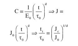
Thus, this model gives the initiation
time as a function of intrinsic material
parameters (through Jc, t0, and d) and
the extrinsic loading and geometry dependent
contributions (contained in J0).
This closed-form prediction of the initiation
time provides a means to evaluate
how material and design characteristics
can directly interact. For instance, a reduction
in material toughness could be
offset with either alterations to the design
or creep resistance. Figure 11 depicts
an example of how crosslinking,
which affects toughness, elastic modulus,
and creep resistance, can result in
a substantial reduction in the initiation
time with modest changes in individual
material parameters.27
Specifying a minimum value of initiation
time as a design requirement
would provide an industry standard for
safety against crack initiation without
undue restriction of flexibility in the
development of new components. The
above model also suggests future directions
of research for material optimization
against crack initiation. For instance,
it is desirable for UHMWPE to
exhibit both a high creep resistance and
fracture toughness, while an increased
elastic modulus beneficially depresses
J0 for a given applied load. As crosslinking
generally both increases creep
resistance and depresses toughness,
its overall influence on crack initiation
could be difficult to predict. Melting
crosslinked UHMWPE reduces its
crystallinity and stiffness, thus elevating
J0. Some highly crosslinked UHMWPE
formulations are oxidatively stabilized
without remelting, and these
newer formulations exhibit improved
fracture toughness and elastic modulus;
however, their relative crack initiation
performance is yet unknown. The
lesson implied by this analysis is that
notch fatigue in UHMWPE is likely
not only governed by fracture toughness
or crack propagation resistance,
but could be dominated by viscous
and elastic effects, and that improved
UHMWPE formulations could exploit
this phenomenon.
RECOMMENDATIONS
Fractures have been observed in
crosslinked UHMWPE acetabular liners
in total hip replacements, and are
likely attributable to the adoption of
a more flaw-intolerant material in a
design containing notches in highly
stressed locations of the component.
Investigation of similar intact components
has revealed that a majority of
these types of device designs using the
crosslinked formulation of UHMWPE
harbored initiated cracks at the same
locations where fractures were previously
observed to initiate. The prevalence
of initiated cracks in these case
series recommends the prevention of
crack initiation as a means to control
fatigue failure in total hip replacements.
The time-dependent analytical crack tip
model presented here provides a simple
framework for evaluating the inherent
impact of material or design alterations
on crack initiation performance.
CONCLUSIONS
The clinical performance of a medical
device depends on many factors and
an understanding of the structure-property-design relationships is essential for
the clinical success of the implant. The
clinical evolution of the three systems
presented in this work were chosen to
illustrate the sophisticated interplay between
design, material selection, structural
properties, processing and clinical
demands; and to illustrate these effects
on the performance of medical device
implants utilizing polymeric materials.
ACKNOWLEDGEMENTS
The authors would like to thank the
NSF and NIH for partial funding of this
research. We would like to acknowledge
Ms. Huayin Wu for assistance with
technical illustration of the first seven
figures and Prof. Clare Rimnac for her
technical insight and discussions with
the authors on this topic.
REFERENCES
1. J.I. Kroschwitz, editor, Polymers: Biomaterials and
Medical Applications (New York: Wiley, 1989).
2. J. Black, Biological Performance of Materials:
Fundamentals of Biocompatibility (New York: Marcel
Dekker, 1999).
3. J.B. Park and J.D. Bronzino, Biomaterials: Principals
and Applications (Boca Raton, FL: CRC Press,
2003).
4. B.D. Ratner et al., Biomaterials Science: An Introduction
to Materials in Medicine (New York: Academic
Press, 1996).
5. J.B. Park and R.S. Lakes, Biomaterials: An Introduction (New York: Plenum Press, 1992).
6. D.W. Howie et al., Clin. Orthop. (1993), N. AM. 24:4
571-581.
7. H.-G. Willert and M. Semlitsch, J. Biomed. Materials
Res., 11 (1977), p. 157.
8. J.L. Gilbert, C.A. Buckley, and J.J. Jacobs, J.
Biomed. Res., 27 (12) (1994), pp. 15331544.
9. R.J. Young and P.A. Lovell, Introduction to Polymers (London: CRC Press, 1990).
10. A.H. Matsumoto et al., Cardiovasc. Intervent. Radiol.,
16 (1993), p. 135.
11. C.A. Fontirroche and S. Querns, U.S. patent 5,
820,594 (1998).
12. S. Gad, Safety Evaluation of Medical Devices (New York: CRC, 2001), pp. 505536.
13. S. Bondurant, V.L. Ernster, and R. Herdman,
Safety of Silicone Breast Implants (Washington, D.C.:
Institute of Medicine National Academy Press, 1999),
pp. 253254.
14. D.A. Kessler, New Engl. J. Med., 326 (1992), pp.
17131715.
15. L.R. Holmich et al., Plastic and Reconstructive
Surgery, 120 (7) (2007), pp. 62S69S.
16. Mentor MemoryGel Silicone Gel-Filled Breast
Implants Product Insert Data Sheet Physician Labeling
Document (Silver Spring, MD: Food and Drug
Administration, 2006)
17. NIH Consensus Development Conference
on Total Knee Replacement (Bethesda,
MD: National Institutes of Health), http://consensus.nih.gov/2003/2003TotalKneeReplacement117html.htm
18. Total Hip Replacement, NIH Consensus Statement,
12 (5) (1994), pp. 131.
19. H.G. Willert, J. Biomed. Mater. Res., 11 (2) (1977),
pp. 157164.
20. D.W. Howie, J. Arthroplasty, 5 (4) (1990), pp.
337348.
21. D.O. OConnor et al., Transactions of 44th Annual
Meeting of the Orthopaedic Research Society (Rosemont, IL: Orthopaedic Research Society, 1999),
p. 816.
22. D.A. Baker, A. Bellare, and L. Pruitt, J. Biomedical
Materials Research, 66A (2003), pp. 146154.
23. S.S. Tower et al., J. Bone Joint Surg. Am., 10
(2007), pp. 22122217.
24. J. Furmanski et al., Catastrophic Rim Fracture of
Four Highly Cross-linked Acetabular Liners (Paper
presented at the Annual Meeting of the Am. Acad.
Ortho. Surg., 2008).
25. W.Y. Shon et al., J. Arthroplasty, 4 (2005), pp.
427435.
26. J. Furmanski et al., In vivo Crack Initiation in Retrieved
Cross-linked UHMWPE Acetabular Liners,
Transactions of the 55th Annual Meeting of the Orthopaedic
Research Society (Rosemont, IL: Orthopaedic
Research Society, 2009).
27. J. Furmanski, C.M. Rimnac, and L.A. Pruitt, Brittle
Fatigue Crack Propagation of UHMWPE and Its Implications
for Total Joint Replacements (Paper presented
at the 14th International Conference on Deformation,
Yield and Fracture of Polymers, Kerkrade, The
Netherlands, 2009).
28. J. Furmanski, E. Feest, and L.A. Pruitt, Static
Mode Fatigue of UHMWPE (Paper presented at the
2nd International Congress on the Mechanics of Biomaterials
and Tissues, Kauai, HI, 2007).
29. J.G. Williams, Fracture Mechanics of Polymers (Chichester, U.K.: Ellis Horwood Ltd., 1984).
Lisa Pruitt is a professor in the Mechanical Engineering
Department, University of California at
Berkeley, Berkeley, CA, and Jevan Furmanski is a
post-doctoral fellow at Case Western Reserve University,
Cleveland, OH. Prof. Pruitt can be reached
at lpruitt@me.berkeley.edu.
|
 Presenting a Web-Enhanced