 LATEST ISSUE |
||||
TMS QUICK LINKS: |
• TECHNICAL QUESTIONS • NEWS ROOM • ABOUT TMS • SITE MAP • CONTACT US |
JOM QUICK LINKS: |
• COVER GALLERY • CLASSIFIED ADS • SUBJECT INDEXES • AUTHORS KIT • ADVERTISE |
|
| Overview: Integrated Computational Materials Engineering | Vol. 58, No.11, pp. 28-35 |
Virtual Aluminum Castings:
An Industrial Application of ICME
John Allison, Mei Li, C. Wolverton, and XuMing Su
| ||||||||||||||||
| ||||||||||||||||
| ||||||||||||||||
|
|
||||||||||||||||
Questions? Contact jom@tms.org. © 2006 The Minerals, Metals & Materials Society |
|
INTRODUCTION Virtual Aluminum Castings (VAC) is a
revolutionary computer-aided engineering
(CAE) process that tightly couples
manufacturing and design analysis into
a holistic system to enable up-front
analysis. It demonstrates the capability
and benefits of the integrated computational
materials engineering (ICME)
paradigm discussed in this special edition
of JOM. Virtual Aluminum Castings is
a suite of integrated computational tools
that enables the rapid development of
durable, cost-effective cast aluminum
powertrain components. It is based on
advanced material models that bridge the
many key dimensional scales from the
atomistic level to the component level.
Using VAC, virtual components are now
designed, cast, heat treated, and tested for
durability on a workstation long before
components are fabricated. The development
of VAC is the culmination of
years of comprehensive research on cast
aluminum. It has been accomplished by
a combination of theoretical, experimental,
and computational technologies and
has involved the development of a deep,
fundamental understanding of dozens of
separate phenomena. This theoretical and
empirical knowledge has been captured
in a computationally efficient software
package within VAC. VIRTUAL ALUMINUM CASTINGS: USING THE ICME METHODOLOGY The central objective of VAC is to significantly reduce the time required to develop and optimize new cast aluminum components and casting/heat-treatment processes. This objective is accomplished by developing and validating a computational capability with four interdependent parts (Figure 1): the accurate simulation of the thermal history of an aluminum component through casting and heat treatment, the prediction of the microstructure that evolves during these manufacturing processes at all locations in a casting (i.e., the local microstructure), the prediction of critical local mechanical properties which result from these local microstructures, and coupling predicted local properties and new damage and residual stress models with finite element analysis (FEA) methods to predict the durability of engine components. Commercial casting simulation software, specifically MagmaSoft™ and ProCast™, and FEA software, specifically ABAQUS™, provide the basic framework for development of these computational capabilities. This methodology provides Ford with the capability to quickly engineer low-cost, durable aluminum castings. The development of VAC required activities in several key areas, specifically:
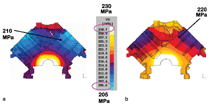
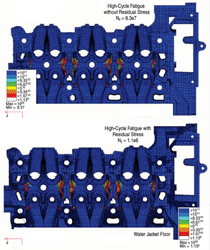
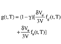
One of the challenges in developing VAC tools was to develop a predictive approach capturing the influence of the manufacturing process history on the mechanical properties. This is a significant challenge because these models must account for metallurgical phenomena that occur at vastly different length and time scales (see Figure 3). For instance, solute diffusion and precipitation in alloys is inherently an atomistic process, but can manifest itself via changes in macroscopic properties (e.g., yield strength or thermal growth). Hence, constructing properties models in VAC requires the utilization and linkage of modeling tools from the atomistic scale, through nanostructure and microstructural length scales, all the way to the macroscopic dimensions, as depicted in Figure 3. Metallurgical features at each of these length scales influence properties in a wide variety of complex ways. Thus, it was necessary to develop a fundamental and quantitative understanding of the manner in which specific properties were influenced by specific metallurgical features acting singularly or in combination. However, to ensure computational efficiency it was important to model only those metallurgical processes and length scales that are critical to the desired outcome. Development of these models required a unique mix of research expertise including experimentalists and theoreticians with extensive knowledge of numerical modeling, metallurgy, physics, and engineering mechanics. Linking Manufacturing Process to Microstructure Commercial software such as ProCAST and MagmaSoft has been used in the past for casting process simulation; however, its primary use has been for determining the castability of geometries. These codes generally do not predict the local microstructures that evolve during casting and heat-treatment processes nor do they predict local mechanical properties resulting from these local microstructures. For cast aluminum, the key microstructural features are microporosity, eutectic phases, and precipitate phases. To predict these local microstructural features it is critical to first be able to accurately predict thermal history during casting and heat-treatment processes. Commercial casting simulation codes have limited success in predicting microstructure in part due to limitations in their heat-transfer coefficient databases. For decades, researchers have attempted to obtain heat-transfer coefficients for different metal-mold interfaces and processes experimentally, analytically, or with inverse modeling approaches. However, for a variety of reasons, it is usually difficult to apply the interfacial heat-transfer coefficients (IHTC) from the literature directly. Chief among these reasons are the dependence of the IHTC on the casting geometry, detailed differences in mold material, quench media, and casting or quenching processes. Therefore, a specialized optimization routine was developed called OptCast,2 which couples MAGMAsoft or ProCast with an optimization program based on an inverse modeling approach. OptCast enabled the development of accurate IHTC for a wide variety of geometries, casting processes, and heat treatment (water quenching) processes. These improved heat-transfer coefficients substantially increase the accuracy of thermal histories predicted by the casting and heat-treatment simulations. Prediction of microstructure and micro-segregation during solidification in a multi-component alloy is a crucial step in understanding and simulating mechanical properties and subsequent in-service performance of cast components. In 319-type aluminum alloys (Al-Si-Cu), the eutectic θ or Al2Cu phase is of particular interest because it affects the subsequent evolution of the precipitation- strengthening phase, θ′ (also Al2Cu), during the aging process. During solution treatment, these eutectic phases slowly dissolve, so it is also important to include this effect. A software tool called MicroMod was developed to couple solid-state diffusion, dendrite arm coarsening, and dendrite-tip undercooling directly with a commercial multi-component phase diagram (CALPHAD) computation tool, Pandat. Results from phase transformation kinetic models such as the commercial tool, Dictra, were used for predicting phase dissolution. MicroMod is capable of predicting secondary dendrite arm spacing and, more importantly, the amount and type of the eutectic phases that evolve during casting and the dissolution of these phases during subsequent thermal treatments. At the nanoscale, accurately predicting the amount and morphology of the precipitation strengthening phase, θ′, is critical. Similar to MicroMod, this precipitate prediction requires an approach that links different modeling techniques. The resulting model, called NanoPPT, was accomplished by linking first-principles atomistic calculations based on density functional theory for the calculation of stable and metastable thermodynamic functions, thermodynamic phase equilibria calculations such as ThermoCalc or Pandat for phase stability, and microstructural evolution models for precipitate kinetics and morphology.3,4 The microstructural evolution models were heavily dominated by empirically derived relationships.6 Ongoing developments are aimed at the incorporation of a multiscale first-principles/phase-field approach, developed to reliably predict θ′ morphologies,6,7 thereby eliminating one of the key empirical components of the current version of NanoPPT. Microporosity is a common microstructural feature that can have a profound influence on properties such as fatigue. The VAC tool MicroPore, a subroutine for commercial casting simulation codes, uses the calculated casting thermal histories to quantitatively predict the relevant characteristics of microporosity. It incorporates the complex, non-linear physics of nucleation and growth of pores. It models both the macroscopic phenomena that control microporosity, including fluid flow and pressure variations in the melt, and the microscopic phenomena, such as segregation of the hydrogen/alloying elements, to accurately predict the local pore size. Linking Microstructures to Mechanical Properties As described, the ICME philosophy was applied to develop the microstructural evolution models in VAC by linking models operating at different length scales. It was also used in the development of the models for prediction of mechanical properties resulting from these microstructures. Yield Strength The authors’ approach for modeling the age-hardening yield-strength behavior of cast Al-Si-Cu alloys utilizes micromechanical models of precipitation strengthening that connect key microstructural parameters for realistic precipitate morphologies (e.g., {100} plates) with the age-hardening response.5 The microstructural parameters of the strengthening θ′ plates measured by transmission-electron microscopy and a combined first-principles/computational-thermodynamics model of θ′ volume fraction8,9 are used in the micromechanical model to predict precipitation strengthening, producing a model that is completely free of fitting parameters. This yield-strength model, called LocalYS, is linked with microstructural evolution models (MicroMod and NanoPPT) to produce a model of the macroscopic, location-dependent yield-strength behavior throughout the cast part. Thermal Growth In Al 319 castings aged for peak strength (e.g., T6), a macroscopic, irreversible dimensional change (termed thermal growth) occurs during extended high-temperature exposure.10 Hence, heat-treatment schedules are often devised in an effort to stabilize the casting with respect to in-service dimensional changes. The unique combination of first-principles atomistic calculations, computational thermodynamics, and experimental measurements used to construct NanoPPT was similarly used to produce a model, called LocalTG, of thermal growth in Al 319.4 The precipitation of Al2Cu (θ′) is the major contributor to thermal growth, and the model, based on θ′ and θ evolution, provides a quantitative and accurate predictor of measured thermal growth. Like the yield-strength model, LocalTG was also made possible only via a linkage with the microstructural models, NanoPPT and MicroMod.3 As an illustrative example of the integration of microstructural evolution, length-scale information, and properties, we examine the general expression for thermal growth g(t,T). Growth is given as a function of time and temperature4 as shown in Equation 1. In this relationship, dVθ′ and dVθ are the volume changes associated with copper atoms going from solid solution to precipitate phases θ and θ′, respectively. These volume changes are determined using first-principles atomic-scale calculations. fθ and fθ' are the fractions of copper involved in θ and θ' phases as a function of time and temperature. These quantities are determined from NanoPPT using a unique combination of first principles, CALPHAD, and empiricism developed for the alloy in question. The factor γ accounts for the fraction of copper lost to eutectic θ phase and is predicted from the solution treatment dissolution model contained within MicroMod. Incorporating this thermal growth model into a time- and temperature-dependent swelling module within ABAQUS enables the prediction not only of the thermal growth that occurs in cast aluminum engine blocks and heads as a function of heat treatment and in-service temperature and time, but also the stresses that develop due to growth in these parts. Combining these tools with residual stress models produces a key tool within the VAC suite for not only process optimization of heat-treatment times and temperatures, but also design optimization of blocks and heads. Thus, thermal growth provides an example where important phenomena occur on, and must be accurately modeled on, scales ranging from Angstroms to meters. Fatigue Properties Fatigue strength is one of the most important properties impacting cast aluminum engine components. The ability to predict the influence of casting history on the local fatigue strength is therefore a key capability within the VAC toolset. The authors’ local fatigue strength model, LocalFS, is based on a novel short-crack growth fatigue model11 that relates the size of micropores to the high-cycle fatigue response. The local pore-size characteristic predicted by the microporosity model described is used, in turn, to predict the local fatigue strength in the critical regions. Figure 4 illustrates the procedural flow necessary to calculate pore size with MicroPore for a casting component and link it to the prediction of local fatigue properties. Linking Material Properties to Performance Prediction The material properties obtained are integrated into engineering analysis by another link: the coupling of material properties to performance prediction, in this case, durability. For that purpose, another critical VAC component, the prediction of residual stresses, was required. Residual Stress Analysis The prediction of residual stresses in complex castings represents a formidable engineering challenge. The residual stresses most concerned in VAC are those formed during heat treatment of cast aluminum cylinder heads and blocks. The QuenchStress VAC module was developed to predict residual stresses due to casting and heat treatment. Residual stresses in a heat-treated cast aluminum engine component are mainly introduced during the quench step following the solution treatment. During this treatment, the component is quickly cooled from around 500°C to much lower temperatures by immersing the component in water, polymer quenchant, or using forced air. The temperature gradient from the surface to the interior of the component leads to non-uniform thermal expansion and non-uniform plastic deformation and residual stresses. The residual stresses generated during quenching are relaxed partially during the aging step of heat treatment. Any attempt to predict residual stresses in a heat-treated aluminum component thus involves thermal analysis for the transient temperature field during quenching and stress analysis for both the quench and aging steps. The thermal analysis of forced air quench processes can be handled reasonably conveniently by commercial computational fluid dynamics (CFD) codes.12 Water quenching is much more difficult to simulate, as it involves the boiling and vaporizing of water on metal surfaces. Due to the limitations of current CFD codes for solving this problem, an inverse modeling approach was adopted using the OptCast software. In this instance, the heat-transfer problem is treated as a boundary-value problem, using temperature-dependent IHTC on the metal surface to represent the complicated thermal activity between water and the metal surface.13 The influence of geometrical features within a component on the IHTC is accounted for by dividing the geometric surface into several groups. A database of temperature-dependent IHTCs is obtained for different water and component conditions. The key to success of a robust residual stress analysis is the material constitutive relation. The material response to loading during the quench process is strongly temperature- and strain-rate dependent. Experimental measurements of stress and strain relations were carried out at isothermal conditions for various temperatures and strain rates. These test data were captured in a unified material relation.12,14 A computationally efficient, user-defined material subroutine called QuenchStress was developed to interface the material relation with the commercial finite-element code, ABAQUS. Durability Prediction Accurate durability prediction routines requires the ability to predict the material stress-strain response and fatigue response during the complex thermal mechanical cycling that occurs in cylinder heads and blocks. For this purpose, the HotStress subroutine was developed. It is based on a unified viscoplastic material relation14,15 and integrates the results of the visco-plasticity model with output from the previously described local yield-strength model. It also accounts for the impact of material aging during both heat treatment and engine operation. The final module of the VAC toolset is a durability model, Hotlife, which predicts how the component responds to a wide variety of loading conditions. These durability models12,15 have been implemented into an ABAQUS postprocessor using the VAC-predicted local properties and residual stress models as inputs. These durability models predict the response of the structure to complex high-cycle, low-cycle, and thermal mechanical-fatigue loading sequences. Normally such durability models are based on a database approach that assumes an average material property with no manufacturing influence on the mechanical properties. The VAC tools are unique in that they account for the influence of the casting and heat-treat process on the variation in local properties as well as the local residual stresses that are produced during the manufacturing processes. Model Validation and Integration into the Engineering Process Despite the many benefits of a tool such as VAC, convincing manufacturing and product engineers to move from a physical world to a virtual world requires them to develop a strong sense of confidence in the methodology. Thus, an essential and integral step of VAC tool development is the experimental validation of these integrated models. This step involved the development of many novel experimental techniques for quantification of such factors as residual stresses12,13 and component durability.16 It also required a comprehensive experimental validation from castings manufactured under a wide variety of casting and heat-treatment process conditions. Figure 5 shows a typical validation of the local yield-strength model. An important aspect of validation is determining, with the target user, the range over which the product may operate and an acceptable degree of correlation. For the yield-strength example shown in Figure 5, the model predictions have an excellent correlation with the experimental measurements in the normal production region and a reasonable correlation even far beyond this region. Another critical success factor was the integration of the VAC toolset into an efficient engineering methodology. This was another challenging aspect of the VAC development. Typically manufacturing simulation is conducted after performance modeling and is used to ensure that a well-designed (from a mechanical perspective) part can be manufactured. For VAC to succeed, it was necessary to reverse these procedures (i.e., the manufacturing simulation must come prior to prediction of the engine component durability). Organizational cultural changes were required as well as development of timing plans and procedures to ensure that critical manufacturing information was available earlier in the process than was previously typical. To ensure that program timing could either be met or accelerated requires that these complex computations can be completed efficiently and that hand-offs between manufacturing CAE and product (performance) CAE are organized and efficient. To accomplish this, substantial effort was expended in the development of computationally efficient, proprietary algorithms and procedures as well as specialized software linking the outputs of casting simulations codes to FEA codes. The product creation process for cast aluminum blocks and heads has traditionally been the costly approach of design→build→test→redesign→build→retest. Manufacturing analysis is traditionally conducted after the design is complete. Subtle manufacturing changes made late in the product development process can lead to engine durability problems and, as a result, delays in launching new products. By providing a holistic analysis environment, VAC enables manufacturing and product engineering to work together simultaneously to solve these problems long before components are cast and engines tested. Examples of how VAC has been used in process selection and optimization and improved component design criteria follow. Manufacturing Process Selection and Optimization Virtual Aluminum Castings also provides a valuable tool to engineers for optimizing the manufacturing process. A hypothetical example is the use of the local yield-strength model to optimize the heat-treatment process for a cylinder block. In this example, the property target for the key bolt boss shown in Figure 7 was given to be 220 MPa. An initial heat-treatment process for this block included 5 h aging at 240°C. As shown in Figure 7, the yield strength at this bolt boss was predicted to be 210 MPa, which is below the property target. Using VAC, a new heat-treatment process, based on aging for 3 h at 250°C, was predicted to increase the yield strength to the desired level. The optimized aging process not only allows the component to meet the property target, but also makes the process faster by reducing the cycle time by two hours. Design Improvement and
Optimization One example of the way VAC tools
led to a design improvement is illustrated
by the ability to predict the spatial
variation in fatigue properties and the
influence of the casting process on these
location-dependent properties. The use
of these local properties is vastly superior
to the use of average or nominal properties
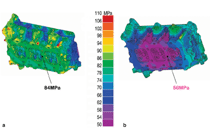
in calculations. As shown in Figure
6, the fatigue properties in complex cast
components can vary by 30–40%. The
use of a nominal property on the upper
end of this range in fatigue calculations
would result in an overly optimistic
calculated life and the potential for a
component that does not pass the engine durability
phase of the product development
cycle. This could require a change
in the geometry or the casting process
resulting in costly and time-consuming
iterative rework of the casting tooling.
In contrast, use of a nominal fatigue
property on the low end of this range could lead to an overly conservative
design. While this would be a durable
design, it would be a heavier and thus
more costly design than required to meet
the design intent of the component. In
contrast, the use of the VAC-predicted
local fatigue properties leads to an accurate
understanding of the influence of
casting on local properties and this
enables a more robust durability prediction.
The use of VAC tools also provides
a capability for putting the right properties
where they are needed throughout
the component. This capability leads to
substantial improvements in product
development timing and an optimum
(e.g., lightweight and low-cost) design. Benefits The benefits demonstrated by the VAC methodology are offered as proof that the promise of ICME can be realized in practice. Linking manufacturing, materials, and design in a holistic CAE environment has resulted in a tool with unsurpassed capabilities. Ford is currently extending this technology to high-pressure die castings, a new process for Ford aluminum engine blocks and magnesium castings. The fundamental framework of VAC can be transferred to the development of similar technologies for non-powertrain (e.g., body and chassis) cast aluminum components in a straightforward manner. The ICME concept is also under investigation to determine its applicability to areas ranging from sheet metal to plastics and to paints. The ability to integrate manufacturing processes and component design through advanced materials models has much promise and is in its infancy. The authors acknowledge the considerable efforts and accomplishments of members of the Virtual Aluminum Castings team within Ford Research and Advanced Engineering and Ford Powertrain Operations. We also acknowledge the efforts and accomplishments of researchers at the University of Michigan, University of Illinois, Imperial College, Pennsylvania State University, and the University of Southern California–Los Angeles with whom we have collaborated in developing the fundamental knowledge base that enabled VAC. 1. John Allison, D. Backman, and L. Christodoulou,
JOM, in this issue. John Allison is senior technical leader, Mei Li is
technical expert, and C. Wolverton and XuMing
Su are technical leaders, all at Ford Motor
Company in Dearborn, Michigan. |

