|
We report on real-time measurements
that enable us to watch the morphology
of whiskers and hillocks forming in
real-time and provide insight into the
mechanisms controlling their growth
and initiation. These measurements
show that whiskers appear to grow out
of a single grain on the surface with
little lateral growth. To understand why
whiskers initiate at specific sites, we
modified the surface using the focused
ion beam to remove the oxide in selected
areas. Whiskers did not grow out of
these uncovered areas, indicating that
the underlying grain structure is important
to whisker growth and it is not sufficient to just remove the oxide barrier.
In comparison with whiskers, we found
that hillock formation is accompanied
by a large amount of grain growth and
often by grain rotation at the surface.
INTRODUCTION
Tin is used heavily in the electronics
industry as a protective coating on copper
conductors because of its excellent
conductivity and resistance to oxidation
and corrosion. Additionally, its low
melting point and ready formation of intermetallic
compounds makes it an ideal
candidate as a solder material for joining
interconnects. In the past, alloying with
Pb has been used to lower the melting
point further and impede the formation
of Sn whiskers13 (i.e., thin filaments of
Sn that grow out of the surface and can
cause system failures by creating short
circuits).4 However, the recent industry
move to Pb-free processing has once again raised concerns about the reliability
issues in electronic components due
to Sn whisker formation.
Over the six decades since their initial discovery,5 a large body of research
has been dedicated to determining the
mechanism of whisker formation.2 Even
so, the whole process is still not well
understood and there is not an accepted
whisker mitigation technique to replace
the addition of Pb. To prevent whiskers,
we need to understand the underlying
driving forces and kinetic processes controlling
their formation. This paper reports
observations made using real time
scanning electron microscopy (SEM) to
monitor whisker and hillock nucleation
and growth. These measurements provide
a window into the detailed process
of how the surface evolves and give insight
into the controlling mechanisms.
See the sidebar for experimental
background.
| HOW WOULD YOU... |
…describe the overall significance
of this paper?
This study follows the evolution of
the surface morphology of pure Sn
coatings over Cu and shows how
whisker and hillock features form.
It shows that these features nucleate
at specific weak grains that can
plastically deform at lower stress
than their neighbors. Just having
a weak surface oxide layer is not
sufficient for a whisker to nucleate.
…describe this work to a
materials science and engineering
professional with no experience in
your technical specialty?
This study measured the real-time
growth of whiskers and hillocks on
Sn coatings over Cu in a FIB/SEM
system. The surface features grow
due to compressive stress in the layer
induced by the formation of Cu-Sn
intermetallic. Long whiskers form
when the grain grows out of the
film without lateral grain growth.
Hillocks form when there is lateral
grain growth accompanying the
growth outwards. Features nucleate
at specific grains that plastically
deform at lower stress than their
neighbors. There is no apparent
weakness in the surface oxide or
other defects before nucleation
occurs.
…describe this work to a
layperson?
Lead has been removed from
tin coatings in electronics
manufacturing because it is harmful
to the environment. This includes the
formation of tin whiskers that can
cause system failures and a shorter
product life. This study provides realtime
observations of whisker growth
on lead-free tin coatings in order to
understand the cause of their growth
and develop mitigation strategies. |
RESULTS
We observed two types of morphologies
for features that grew on the surface
that we classify as whiskers and hillocks.
The term whiskers refers to long
thin filaments that appear to grow out of
a single grain on the surface and show
little observable widening in the SEM
images. Hillocks are more mound-like
in shape. They also appear to initiate
from a single grain but grow in both the
lateral and vertical directions, consuming
neighboring grains as they grow.
We continuously monitored the surface
for periods of 26 days in the SEM/
focused ion beam (FIB) to observe both
whiskers and hillocks nucleating and
growing on the Sn surface. On average,
11 features (approximately 4 of which
were typically whiskers) were observed
over each area of 215 × 185 μm. For
comparison, samples with identical
structures that were kept in air over the
same length of time3,8 had a density of
240 features in a 1 mm square region
after 24 days (slightly more than half of those features were hillocks as opposed
to whiskers). In the following
section we describe our observations
regarding whisker and hillock growth
with accompanying images of the
evolving morphology.
Whiskers
Figure 1 shows the nucleation and
growth of a whisker-type feature at
different time intervals. The feature
does not start to form until 14 h after
the initial deposition. Before that, no
changes can be seen to occur on the
surface (Figure 1a) relative to the first
measurements made at this position.
After 14 h, we observe a rapid change
in the surface morphology around the
position where the whisker will grow.
The image appears to correspond to the
lifting of the oxide on the surface over
the emerging whisker. We refer to this
as cracking although the details of the
change in the oxide cannot be clearly
observed. The crack spreads rapidly
around the base of the forming whisker,
appearing to follow the boundary of the
original grain on the surface. After 20
min. (Figure 1b) it has spread roughly
around half of the grain out of which
the whisker is forming. After 40 min.
(Figure 1c), the crack encompasses the
entire whisker grain and we can observe
the surface of the growing whisker detach
from the surrounding film. For this
particular whisker it took roughly 40
min. for the crack to fully propagate
around the grain and detach from the
Sn surface; in other cases the cracking
process took from 10 to 70 min. No surface
contamination or other defect was
observed on the grain before it started
to form a whisker or on the surrounding
grains. Also no obvious surface
morphology changes were observed in
the surrounding grains after the whisker
started to grow.
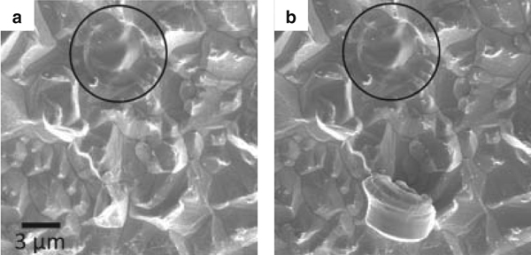
One possible cause of whisker initiation
is a weakness in the oxide above
the grain so that it can crack more easily
and release the whisker. To determine
if this was the case, we deliberately
removed the oxide by using the FIB to
sputter away circular regions to a depth
of 10 nm with various diameters (0.5
μm, 2 μm, and 5 μm). The sample remained
in the FIB after oxide removal
so that no fresh oxide would grow over
the sputtered holes. An example of one
of these sputtered regions is shown in
Figure 2, where the circle drawn on the
figure highlights the region that was
sputtered. We found that the Sn did
not extrude through the holes that were
made in the oxide, indicating that the
underlying grain structure is critical for
whisker nucleation, not just a weak oxide.
The implications of this measurement
are discussed later in this paper.
After the nucleation (oxide-cracking)
stage, we find that the whisker grows at
a nearly uniform rate and in a nearly
constant direction for all the whiskers
observed in these experiments. In contrast,
in other experiments2,7,911 whiskers
have been observed to grow intermittently
with pauses and/or change
direction (i.e., form kinks). In our experience,
we observed this to occur in
whiskers grown from samples kept in
air or measured in an SEM instrument
with a poorer quality base vacuum (4 ×
104 Pa) than the current experiments.
This suggests that the presence of oxygen,
water vapor or other gas may play
a role in the non-uniform growth of
whiskers seen in these cases, perhaps
by regrowing a surface oxide that retards
or modifies the whiskers growth.
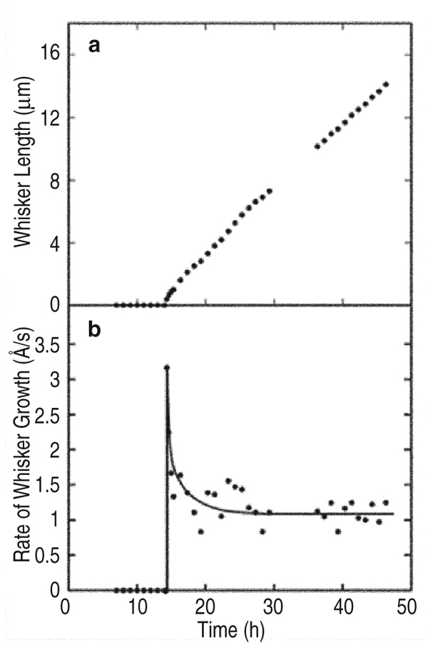
From the measurements of the whisker
length vs. time (Figure 3a), we can
quantify the whisker growth kinetics.
The whisker length is estimated by
measuring the SEM image which does
not account for the angle of growth of
the whisker. Therefore it only provides
a lower bound for the actual length. As
seen in the figure, there seems to be
an incubation period of 14 h, which is
consistent with our previous findings.3,8
The whisker grew to 14 μm in next 34
h, in Figure 3b we plot the instantaneous
growth rate estimated from the
length measurements. As shown in the
figure, the growth rate is initially high
then drops to a steady state rate of 1.14
× 10–10 m/s, similar to the rate found
in the literature.9,12,13 With a diameter
of about 1.1 μm, the volume of Sn extruded from the surface occurs at a rate
of 1.08 × 10⁻²² m3/s. A similar rate was
calculated for the other whiskers found
on the same sample in different areas.
Hillocks
The key difference between whiskers
and hillocks seems to be that the grains
which form hillocks undergo lateral
grain growth whereas the grains forming
whiskers just grow in the upward direction.
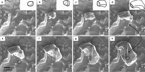
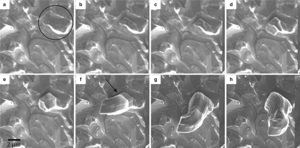
To illustrate this difference, images
taken from regions where hillocks
form are shown in Figure 4 for various
time intervals after the initial deposition.
These images are taken from a sample
with Sn thickness of 4 μm which had a
similar ratio of whiskers to hillocks as
the 2 μm Sn samples. The hillocks start
nucleating after an incubation period of
810 h after Sn deposition. We have included
images from several hillocks to
illustrate different features of growth.
In the first hillock example (Figure 4)
the nucleation appears to start at a single
grain, similar to the initiation of the
whisker. However, unlike the whisker,
the top surface of the hillock rotates as
it grows until the initial oxide-covered
top surface of the hillock is oriented approximately
90° relative to the surface
it started from. To highlight this, a line
drawing of the hillock is shown in the inset
in Figure 4ad. The rotation appears
to occur due to one side of the hillock
growing outward faster than the other.
The extrusion of material is clearly occurring
by addition of Sn at the base of
the hillockthe Sn that is in the hillock
above the surface does not change its
morphology after it first forms.
After the initial rotation, the base of
the hillock starts to widen at the same
time that it is pushing up (Figure 4dh),
indicating an extensive amount of lateral
grain growth by the hillock grain. As the
hillock consumes adjacent grains, the
horizontal growth is roughly constrained
by the grain boundaries on the surface,
appearing to consume an entire neighboring
grain and then slowing down before
consuming the next grain. Some of
the neighboring grains are incorporated
into the growing hillock while other
grains remain unchanged and determine
the hillocks horizontal boundary.
The sequence of growth often proceeds
in a step-wise fashion, with an
increment in horizontal grain-growth
followed by an increment in vertical
growth. This leads to the formation of
horizontal steps (striation marks) on the
side surface of the hillock as it grows.
These striations correspond to the size
of the hillock base at the time when it
was pushed out of the surface so that,
like growth rings on a tree, they can be
used to recreate the history of the hillocks
morphology. Similarly, the vertical
ridge (as pointed to by the arrow in
Figure 4h) forming on the hillock appear
to be the remnants of grain boundaries
between the adjacent grains (pointed to
in Figure 4d) which, as the hillock grain
grew laterally, got absorbed into the
hillocking grain.
It is interesting to note that the surface
oxide around the hillocks base does not
seem to be preventing it from growing
in the upward direction. As the hillock
grows, it carries the oxidized surface
with it. The features that were present
on the Sn surface (for example the white
particle circled in Figure 4e and h) stay
there and get lifted with the hillocks,
and thus the surface of the hillock carries
with it the history of the Sn surface
before the hillock appeared. After 76 h
the lateral grain growth slows down and
stops; at this point the grain boundaries
might have become pinned. After this,
the hillock is only observed to grow in
the upward direction for the duration of
the measurement.
Figure 5 shows a sequence of images
from another hillock on the same
Sn sample, captured over the same time
period but on a different area. In this
case, the hillock appears to start growing
from only a section of a single grain
on the surface. The oxide breaks in the
middle of the grain (highlighted by the
circle) and the part on the left side starts
growing upwards leaving the remainder
of the grain behind (Figure 5b and c).
Similar to the previous example, after
the oxide cracks the original surface of
the grain rotates by approximately 90°
relative to its starting orientation (Figure
5d and e). After this rotation, the
hillock grows primarily in the vertical
direction with little lateral grain growth
(Figure 5fh). However, the tilt angle of
the hillock relative to the surface changes
several times during the growth as
the growth rate at the base varies. The
horizontal marks on the hillock (one of
which is shown by the arrow in Figure 5f) are indications of the point where the
direction of the hillock growth changed.
After roughly 40 h the remainder of the
grain that did not grow initially also
starts growing.
Figure 6 shows surface images from
another hillock (same sample), in which
the growing feature appears to be the
result of 3 or 4 initially separate grains
growing outward together in the form of
a pillar with little lateral growth beyond
what occurred before the hillock started
to grow. After 81 h the hillock starts
to consume an adjacent grain which
changes the growth mode and leads to
rotation of the hillock.
Figure 7 shows one more hillock taken
from the same sample. In this case
one side of the hillocks seems to remain
attached to the surface, perhaps due to
its incapability to completely break the
surface oxide. As the hillock grows, the
surface curves but there is no vertical
growth. Finally it stops after roughly 50
h. The halt in the growth may be due to
the fact that the curving surface curved
by 180° and hit the starting surface. This
appears likely as growth stopped immediately
after hitting the surface. In comparison,
other hillocks on the same sample
continued to grow suggesting that
the driving force for hillock formation
had not been depleted. This again points
out that the surface oxide is important in
deciding the fate of the hillock.
Finally, we found regions in which
grain growth could be observed underneath
the surface with very little upward
movement. This caused enough change
in the surface structure so that the grain
growth could be observed but no formation
of a surface feature could be seen.
DISCUSSION
The growth morphologies can provide
insights into the mechanism controlling
whisker/hillock growth since
their shape and orientation is intimately
related to the way in which atoms are
incorporated into them. In the first part
of the discussion, we consider the significance of the fact that whiskers dont
start to form in regions where we have
removed the surface oxide. In the second
part, we present a brief overview of the
driving forces and mechanisms that we
believe control whisker growth (based
on our own work and that of others) and
explain how we believe they relate to
the morphologies that we observe.
Role of the Surface Oxide in
Whisker/Hillock Nucleation
Tin surfaces exposed to air grow a
tenacious native oxide which plays an
important role in stress evolution by
suppressing relaxation via diffusional
creep of atoms to the surface.10,14,15 Indeed,
it has been shown that removal
of the surface oxide by sputtering3 or
chemical etching16 leads to relaxation of
the stress in the layer. Therefore, it has
been suggested10,15,17 that whiskers form
preferentially at weak spots in the oxide
which can be more easily cracked to allow
material to flow out of the coating.
To address the role of the oxide in
nucleation we used the FIB to remove
the oxide layer at selected regions on the
surface as described above and shown in
Figure 2. Importantly, we found that no
whisker or hillock-type features grew
out of these holes. Moreover, we found
that a hillock-type feature did form at
a distance of only 10 μm from the hole
(Figure 2b) which shows that the surface
modification did not remove the driving
force for hillock formation. We believe
this result clearly indicates that it is not
sufficient to weaken the oxide to initiate
the growth of surface features. Instead,
whisker nucleation is determined by
something in the underlying film.
We also looked at the effect of removing
a larger area of the oxide by
sputtering a region of size 50 × 50 μm.
Even though we would have expected to
see some features forming in a region of
this size, we didnt find any. We interpret
this to mean that modification of a
large area of the oxide can relieve stress
and hence remove the driving force for
whisker/hillock growth.
Growth Modes of Whiskers
Although it is by now generally accepted
that stress is the driving force for
whisker growth,2,3,8,10,11,1720 this knowledge
alone does not explain how whiskering
occurs. To understand it, we must
consider how the stress gets generated,
how this leads to the transport of material
to the whiskering grain and how this
material gets incorporated into the whisker.
At the end of the section, we discuss
how these mechanisms are related to the
results of our FIB/SEM measurements.
The fundamental source of stress in
the Sn layer is the chemical reaction between
the Sn and Cu to form the Cu6Sn5
intermetallic compound (IMC). In Sn
coatings on Cu, IMC formation occurs
primarily on the Sn side of the Cu-Sn
interface due to rapid diffusion of Cu
into Sn.21 Because of this diffusional
asymmetry, the IMC growth is accompanied
by a large volume expansion
that generates stress in the Sn layer. In
previous work,8,22 we have used finite
element analysis (FEA) to simulate the
evolution of the resulting stress field
throughout layers of Sn with columnar
grain structures assuming that stress relaxation
can occur by elastic and plastic
deformation and by grain boundary
diffusion. Two important results of this
work are the average stress saturates in
the Sn (at approximately 12 MPa) due to the onset of plastic deformation; and
the stress is distributed throughout the
Sn layer due to the stress-driven diffusion
of Sn along the grain boundaries.
Without rapid grain boundary diffusion,
the stress would remain much more localized
near the growing IMC particles.
We extended our FEA model of stress
evolution to include whisker growth by
assuming that a whisker forms at a grain
that is weak. By weak we mean that
this grain has a stress relaxation mechanism
that becomes active at a lower
stress than its neighbors (not a lower
elastic modulus). As the IMC continues
to expand and create stress in the Sn, the
stress in the weak grain remains lower
than the surrounding material which
leads to a persistent stress gradient.
This gradient drives diffusion toward
the whisker base so that the whiskering
grain is continually fed material
which can then be incorporated into it
and moved out of the film. The FEA
work showed that measured values of
the grain boundary diffusivity15,23 and
the IMC growth rate3 are sufficient to
explain observed whisker growth rates
and therefore mechanisms of anomalously
fast diffusion are not required.
There are multiple reasons why a
grain may plastically deform at lower
stress than its neighbors (i.e., be
weak). Smetana19 has proposed that
whiskers grow where there are horizontal
grain boundaries (HGB), (i.e., grain
boundaries with a component parallel
to the surface of the film). Addition of
material at the grain boundary results
in an upward force that can cause the
whiskering grain to slide out of the region
in which it is forming. The addition
of extra planes at the interface can also
be thought of in terms of the nucleation
of dislocation loops in the grain boundary
which grow by diffusion-controlled
climb, a non-conservative process that
adds material to the growing whisker. In
support of this picture, many cross-sections
of whiskers show the presence of
horizontally-inclined grain boundaries
near the base of the whiskers. The grain
boundaries may be created during the
plating process or could be the result of
recrystallization. Similarly, Vianco and
Rejent20 have proposed the importance
of dynamic recrystallization (DRX) in
the formation of whiskers. They suggest
that a new recrystallized grain nucleates
to lower the strain energy created
by dislocations in the existing film. The
recrystallization process creates additional
grain boundaries that have a component
parallel to the surface of the film.
Incorporation of material into the strain-free
growing grain at these boundaries
transports material out of the underlying
coating and into the whisker.
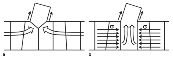
We refer to the HGB and DRX mechanisms
as grain-growth based mechanisms
for whisker formation. They have
in common that additional planes of atoms
are added to the growing whisker
at the interface between the growing
grain and the surrounding material (a
schematic of which is shown in Figure
8a). This generates an upward force on
the grain to push it out of the film which
may occur by grain boundary sliding.19
Whisker growth can also be explained
by an extrusion-based mechanism
if the whisker grain undergoes
plastic shearing at a lower stress than
the surrounding grains. The anisotropic
plastic flow stress of Sn could give rise
to such a strength contrast for a grain
with anomalous orientation relative to
the preferred crystallographic orientation
of the film. In an extrusion-based
mechanism, plastic flow within the
whisker grain due to dislocation glide
can cause extension of the whisker and
transport material out of the film. This
mechanism is analogous to the process
of forming material with a die,24
or squeezing material from a toothpaste
tube.20 This mechanism does not require
the presence of horizontal grain boundaries
which may explain how whiskers
can grow without HGBs, as has been
observed experimentally.25 As the grain
deforms, the adjacent grain boundaries
remain at the yield stress. This induces a
stress gradient which drives long-range
diffusion to the grain along the grain
boundary network. As material arrives
it is incorporated into the deforming
grain along the vertical grain boundaries,
thus providing a continual source
of new volume to replenish the volume
removed by the growth of the whisker
from the surface of the film. The flow of
material within the deforming grain is
represented schematically by the block
arrows in Figure 8b. In this mechanism,
the whisker is the same size as the deforming
grain.
A key feature common to all of the
mechanisms of whisker/hillock growth
proposed above is the presence of a
weak grain, which can relax stress more
effectively than the surrounding grains.
As a result, normal stress across the
grain boundaries adjacent to the weak
grain remains lower than the normal
stress across more distant vertical grain
boundaries within the Sn film. This
sustains a steady-state, non-diminishing
stress gradient that causes material
to be continually transported from surrounding
grains to the whiskering grain
via long-range stress-driven diffusion.26
Growth of a surface feature (whisker or
hillock) from this grain occurs because
the grain deforms so that it can accommodate the material added to it at the
grain boundaries. The stress-induced
deformation may occur by dislocation-mediated glide or by grain-growth
processes with grain boundary sliding.
Most likely both of these mechanisms
are active and work together to produce
the complicated evolution seen on the
surface. As pointed out previously,9,20,27
dislocation-mediated plastic deformation
is probably not the only mechanism
because many whiskers grow in
directions that are not aligned along the
slip systems and they can also change
directions (form kinks) after a period
of growth. However, the complex
morphologies and rotation that we observe
in hillocks would be difficult to
describe by pure grain growth without
plastic deformation occurring as well.
To understand our current work, it
is not necessary to distinguish among
these different deformation mechanisms
since each can produce a flow of
material into whiskers and hillocks that
can be spatially inhomogeneous.
Pure Whisker Growth
In this case, exemplified by the
growth in Figure 1, material that goes
into the whisker appears to come from
deformation of a single grain. There is
no lateral grain growth and the velocity
field is uniform across the whisker so
that it grows in a constant direction (see
Figure 8a and b for schematic illustration).
The lack of lateral grain growth
may coincide with our observation that
the whiskering grain is often smaller
than those surrounding it which would
suppress its tendency to consume its
neighbors. Note that we do not observe
any change in the region of the whisker
before it nucleates, suggesting that
the whiskering grain did not form by
recrystallization though this is not certain;
nucleation below the surface may
not have been visible.
The tilt of the whisker relative to
the surface may come about from the
orientation of the grain boundaries
feeding material into it (grain-growth
mechanism) or the active slip systems
in the grain (extrusion mechanism).
In vacuum, where our measurements
were made, the whiskers grow at a constant
rate with little kinking, suggesting
that the flow of material to the whisker
stays uniform and there is little driving
force to change the orientation. In other
cases where kinks do form, this may be
due to a re-orientation of the underlying
grain boundaries or it may indicate
a retarding effect due to formation of
oxide at the surface. It is also possible
that an alternate slip system has been
activated or that the underlying grain
has been rotated by formation of subgrain
boundaries as seen in TEM.6
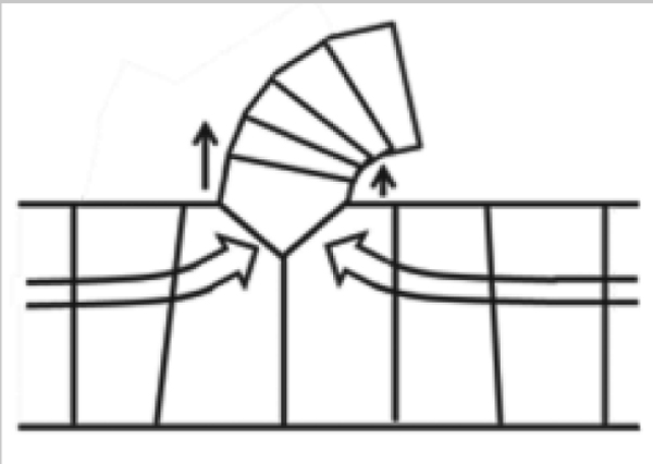
Surface Rotation
During hillock formation, we often
see the surface of the growing feature
rotate significantly (180° rotation in
Figure 7), indicating that the rate of
volume accumulation on one side of
the hillock must be faster than on the
other (schematic in Figure 9). Rotation
of the crystal planes in the hillock
suggests that significant numbers
of dislocations are being injected into
the material as it grows to change the
growth direction. If the feature is being
produced by the extrusion process,
then the rotation may indicate non-uniformity
in the stress surrounding the
grain. Alternatively, if the feature is
growing by a grain-growth process, the
rotation may occur due to a reorientation
of the underlying grain boundaries
feeding material at the base, much
as changing the direction of the nozzle
from a hose can change the direction
of the spray of water. Unfortunately,
we cannot directly observe subsurface
grain boundary changes with the SEM.
However, in several cases (Figures 4
and 5), we observe that the hillock surface
rotates by 90° in the early stages of
growth and then grows out in the vertical
direction. This suggests that the
rotation may occur due to subsurface
motion of the grain boundary which
eventually becomes fixed and therefore
leads to constant vertical growth.
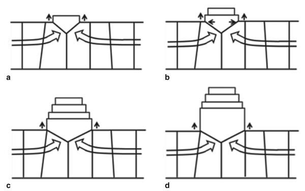
Hillock Formation
The morphology of hillock features
is much more irregular than whiskers
because the shape of the extruding region
can change during their growth.
This occurs because the vertical growth
of the hillock is generally accompanied
by lateral grain growth. The decrease
of the strain energy density in the whiskering
grain (either due to recrystallization
or other forms of stress relaxation)
lowers its chemical potential so that the
whiskering grain may expand by consuming
its neighbors. There is therefore
a dynamic competition between
vertical growth and lateral growth of
the growing grain (shown schematically
in Figure 10) that leads to an alternation between horizontal and vertical
growth, resulting in a wedding cake
morphology (also described by Pedigo
et al.28). Rapid lateral grain growth
along the boundaries between columnar
Sn grains leads to the ridges on
the side of the hillock as has also been
pointed out previously.28 The sequence
of alternation between vertical and lateral
growth can vary at different sites.
In some cases we observe extensive
lateral growth followed by primarily
vertical growth (Figure 4) and in other
cases the opposite sequence (Figure 6).
Therefore, we do not think that there is
a prescribed sequence of grain growth
and lateral growth; the actual morphology
depends upon a balance between
the different processes determined
by the local microstructure and stress
fields.
Unlike whiskers which always seem
to start from a single grain, hillock
growth can start from a variety of configurations. In some cases, the hillock
originates from a single grain (as in
Figure 4) with no apparent change in
the surface or grain structure before it
starts to grow. In other cases (Figure
5) we have seen the hillock form out
of only part of a grain, suggesting that
there was likely recrystallization of
a new grain below the surface before
the growth started. In other cases (Figure
6), several grains appear to have
grown together before the hillock
starts to grow.
CONCLUSION
We have measured the evolution of
whiskers and hillocks on Sn coatings
over Cu. Whiskers grow outward from
a single grain while the more complicated
morphologies of hillocks can be
attributed to a balance between outward
expansion and lateral growth into the
surrounding grains. Our results are consistent
with a picture in which whiskers
and hillocks initiate at certain weak
grains that can activate stress relieving
mechanisms at lower values of stress
than their neighbors; such mechanisms
occur by adding atoms to the base of
the grain (grain-growth based) or initiating
glide processes (extrusion-based).
The hillock shape is difficult to predict
because of its reliance on the details of
the underlying flow field of material
into the whisker. Additional modeling
work is needed to understand how factors
such as the spatial distribution of
the stress and the accommodation rate
on different surfaces of the underlying
grain can alter the morphology of the
growing feature. In terms of mitigation,
these results suggest that the best strategy
would be to develop microstructures
or alloys that better relax stress without
the formation of surface features. If the
stress cant be removed, then better understanding
of the nucleation process
may allow the development of microstructures
that promote hillock formation
over the long whiskers.
ACKNOWLEDGEMENTS
The authors gratefully acknowledge
the support of the NSF-supported
Brown MRSEC (DMR0079964), NSF
(DMR0856229) and help from L.B.
Freund, S. Kumar, and G. Barr.
REFERENCES
1. S.M. Arnold, in Proc. of Electrical Components Conference
(1959), pp. 7582.
2. G.T. Galyon, IEEE Trans. on Elect. Packaging Manuf., 28 (2005), p. 94.
3. E. Chason et al., Appl. Phys. Lett., 92 (2008), 171901.
4. Multiple examples of whisker-induced failures are
documented on the NASA website, http://nepp.nasa.gov/whisker/.
5. K.G. Compton, A. Mendizza, and S. Arnold, Corrosion,
7 (1951), p. 327.
6. K.S. Kumar et al., J. Mater. Res. (2008), pp. 29162934.
7. Research activities in Prof. Eric Chasons Laboratory,
Brown University, Providence, RI, http://www.engin.brown.edu/faculty/chason/research/.
8. N. Jadhav et al., IEEE Trans. on Elect. Packaging
Manuf., 33 (2010), p. 3.
9. W.C. Ellis, D.F. Gibbons, and R.C. Treuting, Growth
and Perfection of Crystals, ed. R.H. Doremus, B.W.
Roberts, and D. Turnbull (New York: John Wiley &
Sons, 1958), pp. 102120.
10. K.N. Tu, C. Chen, and A.T. Wu, J. Mater. Sci.: Mater.
Electron., 18 (2007), pp. 269281.
11. M. Sobiech et al., Appl. Phys. Lett., 93 (2008),
011906.
12. V.K. Glazunova and N.T. Kudryavtsev, Zh. Prikl.
Khim. (S.-Peterburg), 36 (1963), p. 543.
13. N. Furuta and K. Hamamura, Jpn. J. Appl. Phys., 9
(1969), p. 1404.
14. U. Lindborg, Metallurgical Transactions A, 6A
(1975), pp. 15811586.
15. K.N. Tu, Phys. Rev. B, 49 (1994), p. 2030.
16. J.W. Shin and E. Chason, J. Mater. Res, 24 (2009),
pp. 15221528.
17. B.Z. Lee and D.N. Lee, Acta Metallurgica, 46 (10)
(1998), pp. 37013714.
18. C. Xu et al., IEEE Trans. on Elect. Packaging Manuf.
28 (2005), p. 31.
19. J. Smetana, IEEE Trans. on Elect. Packaging
Manuf., 30 (2007), pp. 1122.
20. P.T. Vianco, and J.A. Rejent, J. Electron. Materials,
38 (2009), pp. 18151825.
21. K.N. Tu and R.D. Thompson, Acta Metallurgica, 30
(1982), pp. 947952.
22. E. Buchovecky et al., J. Electron. Mater., 38 (2009),
pp. 26762684.
23. W. Lange and D. Bergner, Phys. Stat. Sol., 2 (1962),
p. 1410.
24. W. Johnson, R. Sowerby, and R.D. Venter, Plane
Strain Slip Line Fields for Metal Deformation Processes,
A Source Book and Bibliography, 1st ed. (New York:
Peragamon Press, 1982), pp. 107110.
25. N. Jadhav and E. Chason (unpublished).
26. L. Reinbold et al., J. Mater. Res., submitted for
publication.
27. G.S. Baker, Acta Metallurgica, 5 (7) (1957), pp.
353357.
28. A. Pedigo et al., Proc. IEEE Electron. Compon.
Conf. (Piscataway, NJ: IEEE, 2008), pp. 14981504.
Nitin Jadhav, Eric Buchovecky, Eric Chason, and
Allan Bower are with the Division of Engineering,
Brown University, Providence, RI 02912, USA. Dr.
Jadhav can be reached at nitin_jadhav@brown.edu. Dr. Buchovecky is currently at General Motors R&D, Warren, MI. |
 Presenting a Web-Enhanced